Ammonia-based hydrogen generation apparatus and method for using same

a hydrogen generation apparatus and ammonia technology, applied in the chemical arts, can solve the problems of imposing significant design challenges, prohibitively large required adsorbent mass of such materials, and inability to provide compressed hydrogen, etc., to achieve enhanced heat transfer and reaction rate, reduce fabrication costs, and enhance heat transfer rate

Inactive Publication Date: 2006-06-01
INTELLIGENT ENERGY INC
View PDF99 Cites 54 Cited by
  • Summary
  • Abstract
  • Description
  • Claims
  • Application Information

AI Technical Summary

Benefits of technology

[0024] It is an advantage of the invention that the reactor can be fabricated from a nonrefactory metal, such as titanium or stainless steel. It is another advantage of the invention that the reaction chamber can be loaded with an ammonia-decomposition catalyst having a light-off temperature below 600° C. Preferred catalysts include catalysts containing ruthenium or nickel. In some embodiments, the catalyst is packed in the reaction channels, while in alternative embodiments, the catalyst is coated on the internal surface of the flow channels in the reaction chamber.
[0025] In one embodiment, mesochannels are incorporated and depend from and extend between the top and bottom plates, which when sealed provides two chambers that are separated by the reactor core, resulting in a thermocatalytic reactor that is functionally similar to that containing the reactor core as described earlier. Modifying the separation plate and the end plates (top and bottom) also provides a reduction in fabrication costs.
[0026] In one exemplary embodiment, mesochannel fluid flow dimensions, to enhance heat transfer and reaction rates, are incorporated not by machining such channels into components such as the top and bottom plates, reactor cores etc, but by incorporating a porous substrate possessing fluid flow dimensions in the mesoscale range. The porous substrate is composed of metals or ceramics, and is provided in intimate contact with metal surfaces that define the reaction chamber and the combustion chamber. It is preferable to use porous metal substrates to enhance heat transfer rates from the combustion chamber to the reaction chamber. Suitable exemplary candidates of porous metal substrates include meshes, felts and fully sintered, open cell reticulated/foam substrates that are available from Porvair, Inc (Hendersonville, S.C.). For example, metal substrates with a pore size of 10 to 40 pores per inch (PPI) offer pore diameters, and therefore flow dimensions, that are in the mesoscale range of about 0.5 mm to about 2.0 mm. Such porous metal foams are available in materials that can handle hig

Problems solved by technology

Merely providing compressed hydrogen is not always a viable option, because of the substantial volume that even a highly compressed gas occupies.
One of the challenges of utilizing ammonia to produce hydrogen for a fuel cell is that H/AFCs do not tolerate ammonia in the hydrogen feed gas, so the trace amounts of ammonia in the H2/N2 gas mixture produced by an ammonia cracker must be removed before the mixture is supplied to a fuel cell.
Commercially available ammonia adsorbents (e.g., acid-impregnated carbon) can be used for this purpose, but the required adsorbent mass of such materials can be prohibitively large if the ammonia-cracking reactor does not provide high conversion efficiency.
However, using such a high reaction temperature imposes significant design challenges.
These materials often require complex fabrication techniques, such as diffusion bonding, as opposed to more conventional brazing or laser welding techniques tha

Method used


Image

  • Ammonia-based hydrogen generation apparatus and method for using same
  • Ammonia-based hydrogen generation apparatus and method for using same
  • Ammonia-based hydrogen generation apparatus and method for using same

Examples


Embodiment Construction

[0068] Particular embodiments of the invention are described below in considerable detail for the purpose of illustrating its principles and operation. However, various modifications may be made, and the scope of the invention is not limited to the exemplary embodiments described herein.

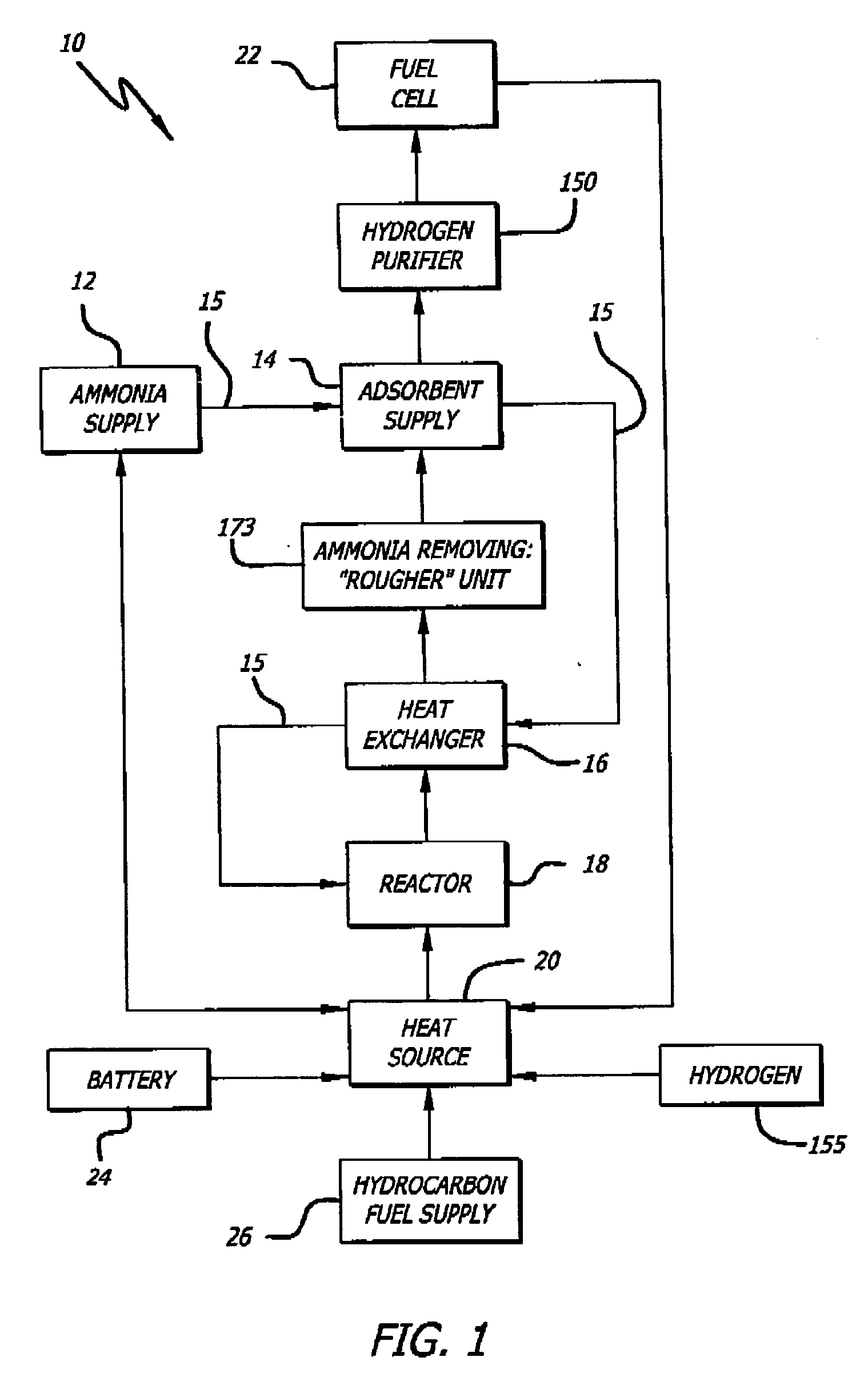
[0069] An exemplary ammonia-based hydrogen generation apparatus 10 shown in FIG. 1 includes an ammonia supply 12, an adsorbent supply 14, a heat exchanger 16, an ammonia dissociation reactor 18 containing a catalyst 86 (FIGS. 9 and 10), and a heat source 20. The embodiment shown in FIG. 1 also includes a fuel cell 22. However, fuel cell 22 is not a required component of an ammonia-based hydrogen generation apparatus.

[0070] The ammonia supply 12 is a pressure vessel containing liquefied ammonia. Those of ordinary skill in the art will appreciate that such pressure vessels are commonly employed and readily available. The ammonia can be liquefied by compression (114 pounds per square inch) and / or by c...


PUM

PropertyMeasurementUnit
Temperatureaaaaaaaaaa

Abstract

The present disclosure provides teachings relating to ammonia-based hydrogen generation apparatus and associated methods of use. Exemplary methods and apparatus comprise a thermocatalytic hydrogen generation reactor which includes a reaction chamber containing a catalyst-coated substrate, and a combustion chamber containing a catalyst-coated substrate. Exemplary catalyst-coated substrates include, but are not limited to, metal foam, monolith, mesh, ceramic foam or ceramic monolith.

Description

RELATED APPLICATIONS [0001] This application is a continuation-in-part of U.S. application Ser. No. 10 / 469,464 filed Aug. 29, 2003, which is a national phase filing of International Application No. PCT / US02 / 06767, filed on Mar. 4, 2002, which claims priority to U.S. Provisional Patent Application No. 60 / 272,806, filed Mar. 2, 2001, all herein incorporated by reference in their entirety. [0002] This Application is also a continuation-in-part and claims priority to U.S. application entitled “Hydrogen Generation Apparatus And Method For Using Same” filed on Apr. 12, 2005 attorney docket number, 73358-032500, which is a continuation-in-part of U.S. application Ser. No. 10 / 476,015 entitled “Hydrogen Generation Apparatus And Method For Using Same”, which is a national phase filing of PCT International Application No. PCT / US02 / 12822, filed on Apr. 23, 2001, all of which are herein incorporated by reference in their entirety. [0003] This application is also a continuation-in-part and claims...

Claims


Application Information

Patent Timeline
IPC IPC(8): C01B3/04
CPCB01J19/249B01J23/42B01J23/462B01J23/755B01J35/04B01J35/06B01J2219/00011B01J2219/00155B01J2219/2453B01J2219/2459B01J2219/2464B01J2219/2465B01J2219/2466B01J2219/2467B01J2219/247B01J2219/2474B01J2219/2479B01J2219/2481B01J2219/2485B01J2219/2486B01J2219/2493B01J2219/2495B01J2219/2497C01B3/047C01B3/56C01B2203/041C01B2203/042C01B2203/043C01B2203/0465C01B2203/048C01B2203/0485C01B2203/066C01B2203/0811C01B2203/0822C01B2203/0827C01B2203/085C01B2203/0883H01M8/04022H01M8/0612H01M16/006Y02E60/364Y02E60/50Y02E60/36Y02P20/10Y02E60/10C01B3/04
Inventor CHELLAPPA, ANANDPOWELL, MICHAEL ROY
Owner INTELLIGENT ENERGY INC
Why Eureka
Try Eureka