Electromagnetic wave applicator
- Summary
- Abstract
- Description
- Claims
- Application Information
AI Technical Summary
Benefits of technology
Problems solved by technology
Method used
Image
Examples
first embodiment
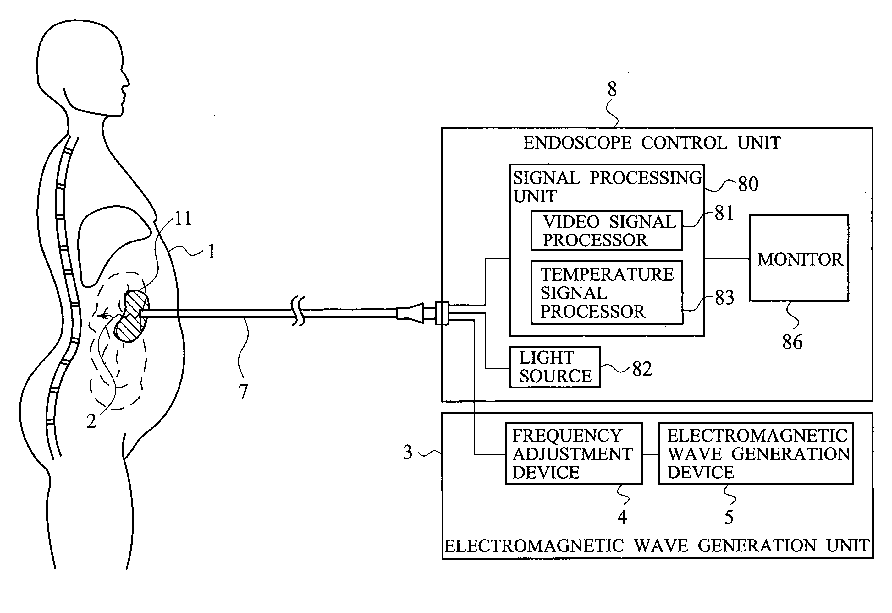
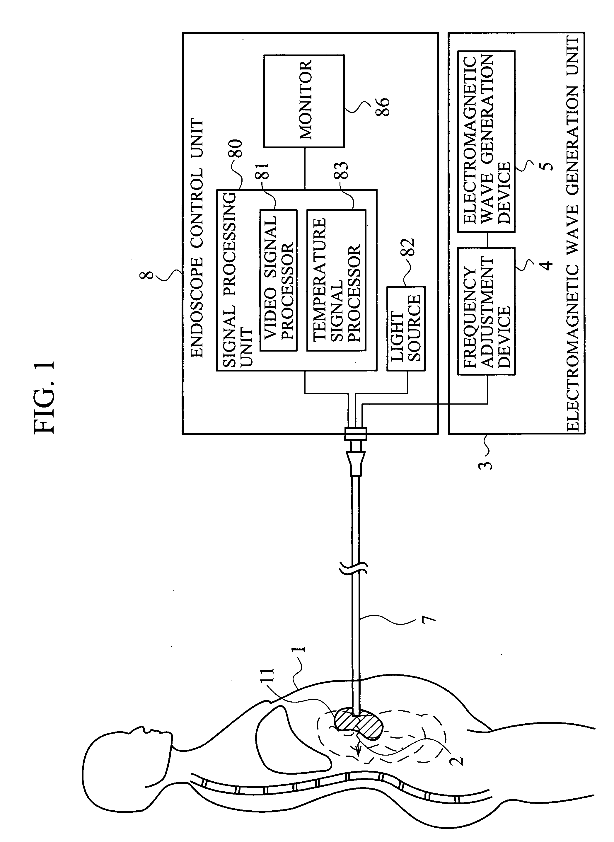
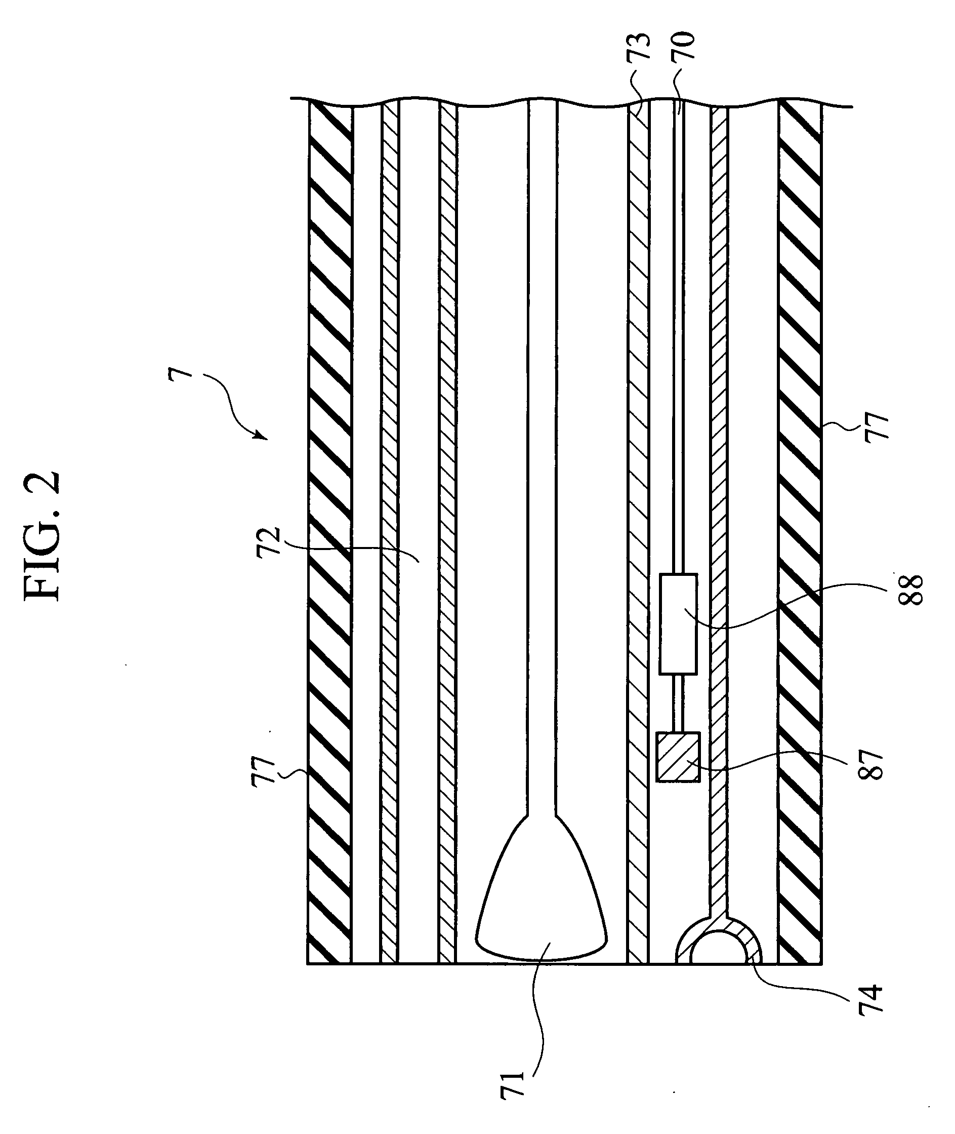
[0036] As shown in FIGS. 1 and 2, an electromagnetic wave irradiation tool according to a first embodiment of the present invention is medical equipment, encompassing an electromagnetic wave generation unit 3 configured to generate an electromagnetic wave 2 having a frequency equal to the characteristic frequency (or “natural frequency”) of a microorganism (causative agent) 11, and a narrow tube (endoscope probe) 7 having a 0.1 mm-20 mm outside diameter. The endoscope probe 7 has an electromagnetic wave irradiation terminal 74 configured to irradiate the electromagnetic wave 2 at the tip of the narrow tube. The narrow tube 7 further encompasses a light guide (optical waveguide) 72, configured to transmit light so that the light can irradiate the biological body, and a temperature detecting unit (a temperature-detecting terminal) 73 configured to detect temperature of the microorganism 11, as shown in FIG. 2. Although in FIG. 1, the narrow tube 7 is so represented that the narrow tub...
second embodiment
[0054] As shown in FIG. 9, an electromagnetic wave irradiation tool according to a second embodiment of the present invention is medical equipment encompassing an antenna-supporting member 60, a plurality of antennas (the patch antennas) 61a, 61b, 61c, . . . provided on a wall surface of the antenna-supporting member 60, and an electromagnetic wave generation unit 3 configured to supply an electromagnetic wave 2, which has a frequency equal to the characteristic frequency of the subject microorganism (causative agent) 11, to the antennas 61a, 61b, 61c, . . . . The antenna-supporting member 60 and the plural the patch antennas 61a, 61b, 61c, . . . , implement an antenna array 6. The antenna-supporting member 60 has a cylinder-shaped geometry so that and a biological body 1 can lie in the inside of the cylinder. As shown in FIG. 10, a plurality of the patch antennas 61a, 61b, 61c, . . . , 61t are arranged in the inner wall of the antenna-supporting member 60 in a matrix-shape. The plu...
third embodiment
[0064] An electromagnetic wave irradiation tool according to a third embodiment of the present invention is medical equipment encompassing a blood irrigation system 9 having a blood-draw line 93 configured to draw blood from the biological body 1 and a blood-return line 94 configured to return the blood to the biological body 1, an electromagnetic wave irradiation unit (antenna array) 6 configured to irradiate an electromagnetic wave having a frequency equal to the characteristic frequency of a microorganism (causative agent) existing in the blood in the blood-draw line 93, and an electromagnetic wave generation unit 3 configured to supply the electromagnetic wave to the electromagnetic wave irradiation unit (antenna array) 6. The configuration of the electromagnetic wave generation unit 3 is similar to the configuration already explained in FIG. 1, and overlapping or redundant description may be omitted in the third embodiment.
[0065] As shown in FIG. 12, the blood irrigation syste...
PUM
 Abstract
Description
Claims
Application Information
 - R&D
- Intellectual Property
- Life Sciences
- Materials
- Tech Scout
- Unparalleled Data Quality
- Higher Quality Content
- 60% Fewer Hallucinations
Browse by: Latest US Patents, China's latest patents, Technical Efficacy Thesaurus, Application Domain, Technology Topic, Popular Technical Reports.
© 2025 PatSnap. All rights reserved.Legal|Privacy policy|Modern Slavery Act Transparency Statement|Sitemap|About US| Contact US: help@patsnap.com


