Visible light-reflecting member

a technology of visible light and reflective member, which is applied in the direction of superimposed coating process, lighting and heating apparatus, instruments, etc., can solve the problems of low light utilization efficiency, increase in thickness and weight, increase in size of guide plate to be used, etc., and achieve the effect of improving corrosion resistan

Inactive Publication Date: 2006-09-28
FOUND FOR ADVANCEMENT OF INT SCI
View PDF6 Cites 8 Cited by
  • Summary
  • Abstract
  • Description
  • Claims
  • Application Information

AI Technical Summary

Benefits of technology

[0045] Further, according to a still further aspect of this invention, there is provided an aluminum thin film reflecting member that enables uniform film formation even with respect to the whole surface of a large-size reflecting plate such as a reflecting plate for a backlight unit of a large-size flat panel liquid crystal display of 28 inches or more.
[0046] Moreover, according to a yet further aspect of this invention, there is provided a reflecting member manufacturing method in which an aluminum thin film is plasma-oxidized by the use of oxygen radicals produced by a plasma in a noble gas containing a small amount of oxygen so as to form an aluminum oxide passive coating film, thereby being capable of remarkably improving corrosion resistance while maintaining reflectance.

Problems solved by technology

However, in the large-size flat panel liquid crystal display of 28 inches or more, a light guide plate to be used increases in size and therefore increases in thickness and weight and thus in cost.
However, since no directivity exists in reflecting light, much light disappears on the wall surfaces and so on and thus the utilization efficiency of light is low.
As a result, there is a drawback of increasing the power consumption.
As a result, reflecting light is colored so that it is not preferable.
In this case, since silver is quite expensive, an aluminum ingot is normally used.
When use is made of an aluminum reflecting plate formed by rolling an ingot, it is necessary, for forming the fine surface structure, to carve such a structure per plate and further it is difficult to accurately control the surface roughness of a reflecting substantially flat or curved surface.
Further, since aluminum has a high specific gravity of 2.71, the weight of the reflecting plate itself becomes large in the case of the aluminum reflecting plate formed by rolling the ingot and therefore it is difficult to actually use it as the reflecting plate in the backlight unit for the large-size flat panel liquid crystal display requiring an reduction in weight.
However, silver itself is expensive and has a drawback of reacting with a very small amount of sulfide (sulfur dioxide or hydrogen sulfide) in the air so as to be blackened and reduced in reflectance.
Further, it is necessary to apply various coatings on the silver thin film so that the silver thin film reflecting plate becomes more expensive and thus is not suitable as the reflecting plate for the backlight unit for the large-size flat panel liquid crystal display having a large area.
However, the aluminum thin film formed by the conventional deposition method is amorphous so that configuration on an atomic level is not elaborate, and therefore, it is not possible to improve the reflectance to 92% or more.
However, a problem has been that the method is not practical because those films should be formed in a number of layers on the aluminum thin film so that the members and processes increase in number to raise the cost and because it is quite difficult to uniformly perform such coating.
Further, it has conventionally been difficult to form a practical flat or curved surface portion having a surface roughness (Ra) of 40 nm or less and, in addition, difficult to implement uniform formation of a deposition thin film itself over the whole surface of the substrate following the increase in size thereof.
Consequently, even if the calculated fine surface shape is formed to control the reflecting light, the luminance nonuniformity cannot be completely controlled.
However, a drawback has been that the thin film formed by the conventional sputtering method as described above is subjected to polycrystallization, i.e. a number of crystal plane orientations appear on the film surface and spaces are formed among crystals, and therefore, a completely elaborate film cannot be formed so that the reflectance has an upper limit of about 92% like the deposited film.
However, since the natural aluminum oxide coating film is formed by the molecular oxidation reaction, the film is not uniformly oxidized to the inside so that the film thickness becomes unequal and, further, since the chemical composition near the aluminum interface after the oxidation is not stoichiometric, i.e. lacking oxygen atoms, it is the film with many defects and is not fully capable of stress relaxation and, as a result, the inside aluminum layer is subjected to corrosion and therefore it cannot sufficiently serve as a protective layer.
However, since the aluminum anodically oxidized film is formed by the oxidation caused by oxygen ions and is a porous oxide film having microholes due to a manufacturing method, a stress remains to cause occurrence of microcracks due to a change in external environment such as temperature and humidity, and moisture or the like infiltrates into the microholes.
Therefore, the aluminum anodically oxidized film cannot completely prevent corrosion of an aluminum layer.
However, this method not only reduces the reflectance and increases the processes and members in number to raise the cost, but also makes it impossible to accurately reproduce the fine surface shape for controlling the light reflection direction, and therefore, is not appropriate.

Method used


Image

  • Visible light-reflecting member
  • Visible light-reflecting member
  • Visible light-reflecting member

Examples


Embodiment Construction

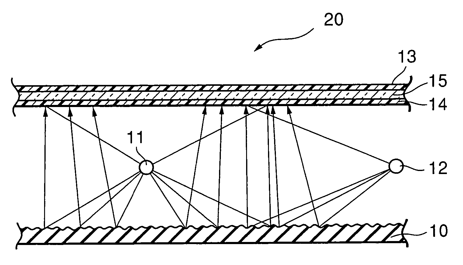
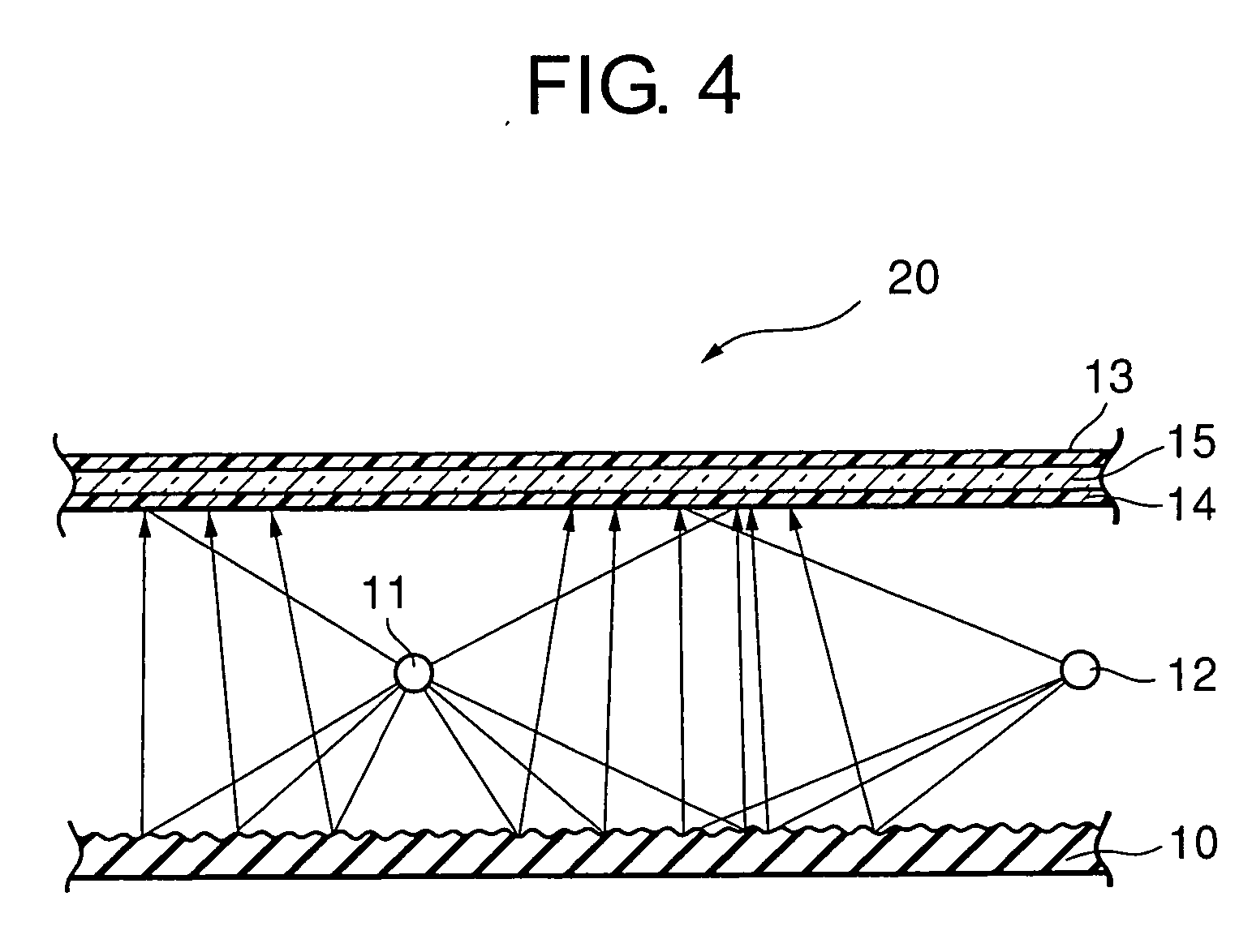
[0052] In assiduously repeating researches on a relationship between aluminum plane orientation and visible light reflectance, the present inventors have carried out sputtering film formation that can control the plane orientation and is capable of uniform film formation even over the whole surface of a large-size substrate and examined the reflectance, and obtained knowledge that selective formation of a particular plane orientation is a very effective means for reliably improving the reflectance in the visible light range. In other words, the present inventors have discovered a technique of causing more (111) planes to remain in a thin film by performing the sputtering film formation under specific conditions, found out that the reflectance in that event is high, and conceived this invention.

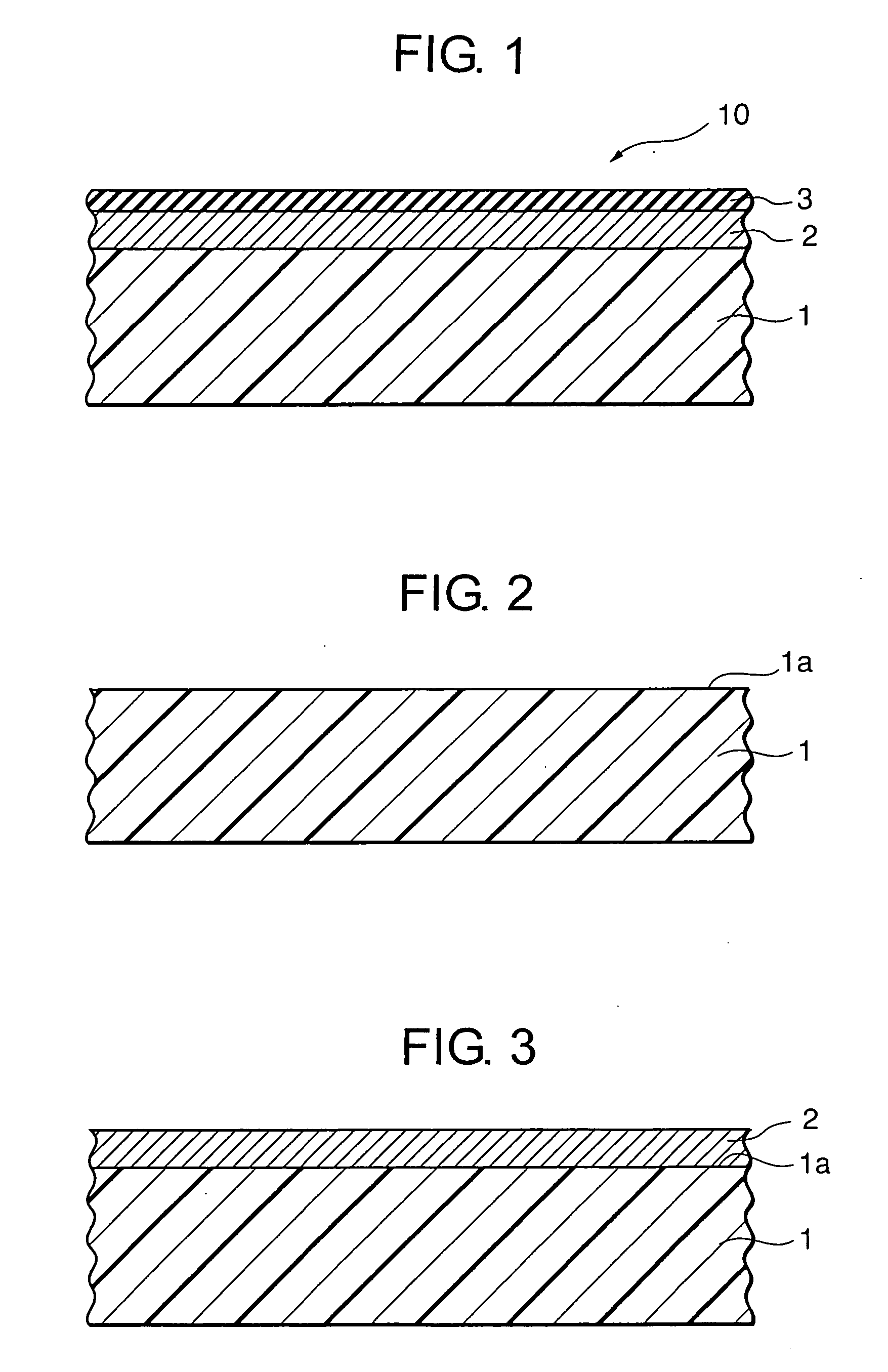
[0053] At first, this invention will be described more specifically. FIG. 1 is a partial schematic sectional view showing one example of a visible light reflecting plate of this invention and...


PUM

PropertyMeasurementUnit
Raaaaaaaaaaa
sizeaaaaaaaaaa
reflectanceaaaaaaaaaa

Abstract

A visible light-reflecting member is disclosed which uses a plate or a film for reflecting visible lights, whose reflective surface is provided with an aluminum thin film having an aluminum purity of not less than 99 mass % and an X-ray diffraction pattern wherein, among peak intensities ascribed to aluminum, the peak intensity ascribed to the (111) plane is higher than the total of the other peak intensities.

Description

TECHNICAL FIELD [0001] This invention relates to a reflecting member used for reflecting a visible light source and, in particular, relates to a visible light reflecting member suitable as a reflecting plate for use in a backlight unit for a large-size flat panel liquid crystal display having a screen diagonal of 28 inches or more. BACKGROUND ART [0002] A reflecting plate is used for reflecting a visible light source. The reflecting plate contains a diffuse reflecting plate applied with white paint or containing diffusing beads, a polished metal plate, and a reflecting plate in the form of a thin film obtained by stacking metal atoms on a substrate. [0003] These visible light reflecting plates are widely used in various applications such as a backlight unit for a liquid crystal display, a reflecting plate for an indoor fluorescent lamp, a reflective layer of a recording medium such as a CD or a DVD, and a vehicle or indoor mirror. [0004] Recently, large-size flat panel displays have...

Claims


Application Information

Patent Timeline
Patent Type & Authority Applications(United States)
IPC IPC(8): F21V7/00C23C14/14C23C14/20C23C14/34C23C28/00C23C30/00F21V7/22F21Y103/00G02B5/08G02F1/1335G02F1/13357
CPCC23C14/205C23C14/345C23C28/322C23C28/345C23C30/00G02B5/08G02F1/133553C23C14/14C23C14/24G02F1/1335
Inventor OHMI, TADAHIROMORIMOTO, AKIHIROTANAHASHI, NAOKI
Owner FOUND FOR ADVANCEMENT OF INT SCI
Why Eureka
Try Eureka