
Purification of organic solvent fluids

a technology of organic solvents and fluids, applied in the direction of ion exchangers, water/sewage treatment by ion exchange, separation processes, etc., can solve the problems of circuit failure, negative impact on circuit performance, negative impact on voltage stability and drift of semiconductor devices

Inactive Publication Date: 2007-04-19
MULLEE WILLIAM H
View PDF21 Cites 10 Cited by
  • Summary
  • Abstract
  • Description
  • Claims
  • Application Information

AI Technical Summary

Benefits of technology

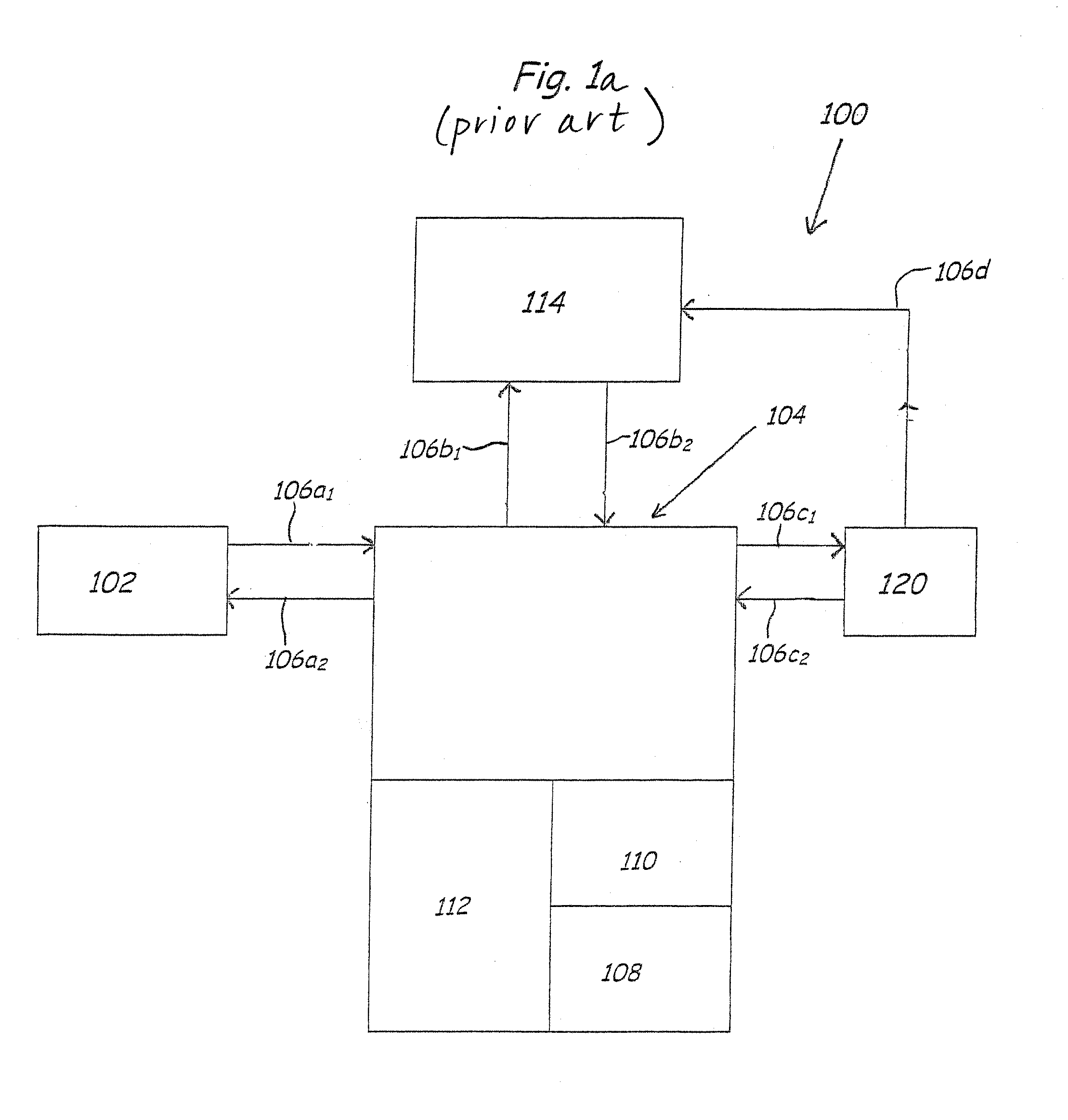
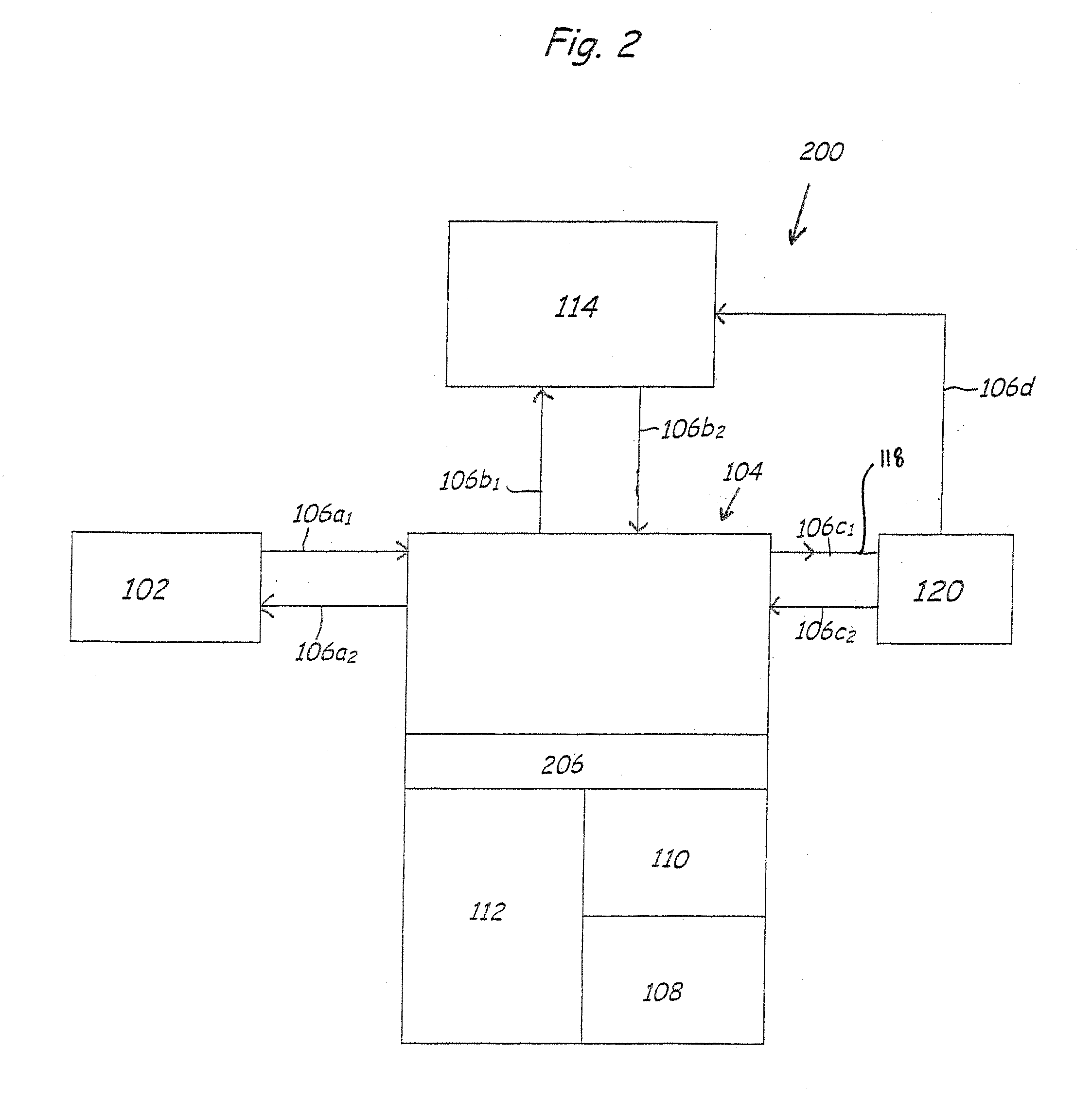
[0017] An object of the present invention is, therefore, to provide a cost-efficient method of and system for purifying and maintaining the purity of organic solvent fluids that are contained within a chemical purification system and that become contaminated during manufacture, use, shipment, or handling.
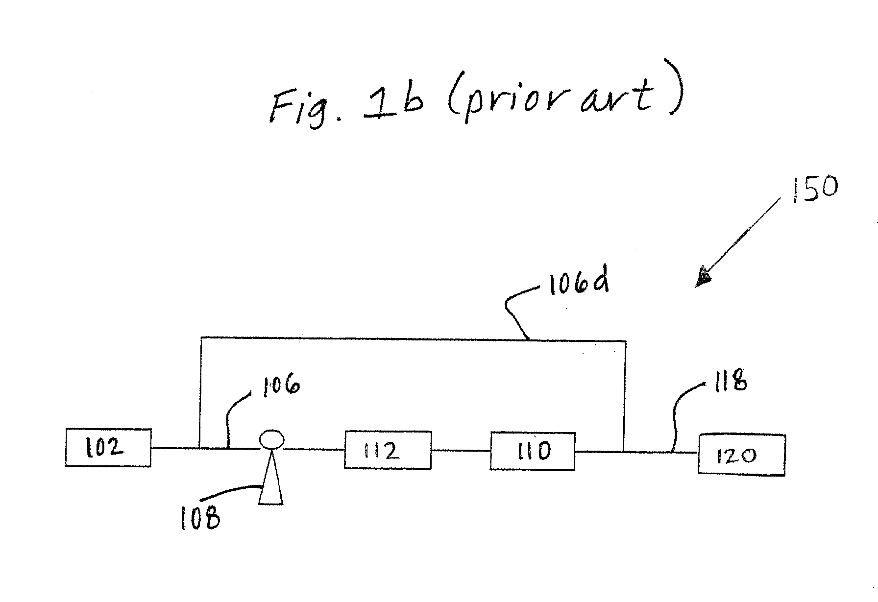
[0019] The chemical distribution or purification system of the present invention preferably includes a return chemical flow pathway that recirculates the purified organic solvent fluid through the vessel containing ion-exchange media. The degree of purification may thus be adjusted by varying the number of passes the organic solvent fluid makes through the vessel. Because the purity level increases with increased ion-exchange media contact and because controlling the number of passes the organic solvent fluid makes through the ion-exchange media enables incremental adjustment of the concentration of impurities to achieve a desired overall purity, the system operator may accurately produce organic solvent fluid having a desired purity.
[0020] The chemical distribution or chemical purification systems of the present invention have the further advantage of allowing the operator to maintain a constant flow of organic solvent fluid within the system and to thereby reduce the incidence of changes in flow rate that cause impurities to dislodge from the system equipment. Similarly, the chemical distribution or chemical purification systems of the present invention facilitate the controlled purification of organic solvent fluids by mixing purified organic solvent fluid with lower purity organic solvent fluid at various ratios to change the efficiency of the system. For example, by increasing the flow rate while maintaining a constant feedstock flow rate, the overall efficiency of the systems may be increased.

Problems solved by technology

The lower purity forms of these organic solvent fluids may contain undesirably high amounts of particulate matter and various other impurities including water, trace metals, and other ions, all of which can negatively impact circuit performance.
For example, the presence of excess chloride ions may cause corrosion to form on metal features of the circuit, resulting in circuit failure.
Also, the presence of excess metal ions in some dielectric materials can negatively affect the voltage stability and drift in semiconductor devices.
While this level of purity is acceptable for most industries, it is unacceptable for the above-identified industries, which require organic solvent fluids having trace metal element or ionic impurity levels of less than one part per billion (ppb).
Because there are various opportunities for the purified organic solvent fluid to be contaminated, a second concern is in-system contamination.
Thus, if the incoming containers of organic solvent fluid having one concentration of impurities are added to existing amounts of organic solvent fluids having a different concentration of impurities, the resultant chemical purity levels within the entire chemical distribution system and / or at the end-use point of connection may be adversely affected.
Also, the organic solvent fluid may be contaminated as a result of use and exposure to contaminated equipment or to the articles of manufacture.
Further, semiconductor wafers and flat panel displays are often processed using repeated immersion cycles in which the wafers or displays are dipped into and out of multiple baths for cleaning purposes, resulting in contamination of the liquid in the baths.
As a result, the high purity organic solvent fluids may be further contaminated by the manufacturing equipment and the existing liquids therein.
Maintaining a consistent process chemical purity level is especially important in the semiconductor and electronics manufacturing industries, because any variation in impurity concentration can adversely impact the stability of the manufacturing system and significantly reduce the quality of the final product.
However, this process is very expensive because it necessitates replacing the expensive high purity organic solvent fluids and because the manufacturer has to dispose of the resultant hazardous waste.
However, this is also very expensive because each of the pleated TEFLON™ filters, for example, costs between about $500 and about $5,000.
Further, the replacement process may require shutting down the entire system.

Method used


Image

  • Purification of organic solvent fluids
  • Purification of organic solvent fluids
  • Purification of organic solvent fluids

Examples


example ii

Purification of Acetonitrile

[0060] The above-described procedure was used to purify a sample of acetonitrile using a 8:5 mixture of Sybron A-641 and CFP-110 resins respectively. The acetonitrile sample was passed through the ion-exchange media six times before the purity of the sample was analyzed. A comparison of the level of metallic contamination of the raw sample and the purified sample is provided in Table II.

TABLE IIAn Analysis of the Concentration of Metallic Contaminants in a PurifiedSample of AcetonitrileDetectionConcentration ofConcentration ofLimits (ppb)Raw Sample (ppb)Purified Sample (ppb)Aluminum0.05Antimony0.05Arsenic0.10Barium0.01Beryllium0.05Bismuth0.05Boron0.100.410.61Cadmium0.01Calcium*0.10Chromium0.05Cobalt0.01Copper0.05Gallium0.01Germanium0.05Gold0.10Iron*0.10Lead0.05Lithium0.05Magnesium0.05Manganese0.05Molybdenum0.05Nickel0.05Niobium0.05Potassium*0.10Silver0.05Sodium0.105.6Strontium0.01Tantalum0.05Thallium0.01Tin0.05Titanium0.050.29Vanadium0.05Zinc0.050.078Z...

example iii

Purification of Ethylene Glycol

[0062] The above-described procedure was used to purify a sample of ethylene glycol using a 4:3 mixture of Sybron A-641 and CFP-110 resins. The ethylene glycol sample was passed through the ion-exchange media once before the purity of the sample was analyzed. A comparison of the level of metallic contamination of the raw sample and the purified sample is provided in Table III.

TABLE IIIAn Analysis of the Concentration of Metallic Contaminants in a PurifiedSample of Ethylene GlycolDetectionConcentration ofConcentration ofLimits (ppb)Raw Sample (ppb)Purified Sample (ppb)Aluminum0.052.90.79Antimony0.050.090Arsenic0.100.028Barium0.012.3Beryllium0.05Bismuth0.05Boron0.100.740.52Cadmium0.010.230.016Calcium*0.101300.60Chromium0.050.69Cobalt0.010.053Copper0.050.830.44Gallium0.010.94Germanium0.05Gold0.10Iron*0.1019013Lead0.050.710.17Lithium0.05Magnesium0.0513Manganese0.050.950.063Molybdenum0.05Nickel0.050.570.065Niobium0.05Potassium*0.10421.5Silver0.05Sodium0....


PUM


Abstract

A chemical distribution system having improved organic solvent fluid purity and consistency includes a vessel containing ion-exchange media positioned within a fluid flow pathway such that the organic solvent fluid passes through the ion-exchange media, thereby effecting removal of undesired impurities. Different embodiments of the invention position the vessel at varying locations within the fluid flow pathway. The chemical distribution system also preferably includes a return chemical flow pathway that recirculates purified organic solvent fluid through the ion-exchange media-containing vessel and thereby enables the system operator to conduct incremental adjustment of the solvent purity until a desired overall purity is attained.

Description

RELATED APPLICATIONS [0001] This application is a divisional of U.S. patent application Ser. No. 10 / 231,547, filed Aug. 29, 2002, which is a continuation-in-part of U.S. patent application Ser. No. 09 / 327,975, filed Jun. 8, 1999, which claims priority from U.S. Provisional Patent Application No. 60 / 088,579, filed Jun. 9, 1998, and claims priority from U.S. Provisional Patent Application No. 60 / 315,918, filed Aug. 29, 2001.COPYRIGHT NOTICE [0002]®2002 PPT Technologies, LLC. A portion of the disclosure of this patent document contains material which is subject to copyright protection. The copyright owner has no objection to the facsimile reproduction by anyone of the patent document or the patent disclosure, as it appears in the Patent and Trademark Office patent file or records, but otherwise reserves all copyright rights whatsoever. 37 CFR 1.71(d). TECHNICAL FIELD [0003] The present invention relates generally to the purification of organic solvent fluids and particularly to the pur...

Claims


Application Information

Patent Timeline
Patent Type & Authority Applications(United States)
IPC IPC(8): B01D15/04B01J39/04B01J41/04B01J47/00B01J47/02
CPCB01J39/043B01J41/043B01J47/00B01J47/026B01J47/14B01J39/05B01J41/05
Inventor MULLEE, WILLIAM H.
Owner MULLEE WILLIAM H
Learn More