Chrome coated surfaces and deposition methods therefor

a technology of chrome coating and deposition method, which is applied in the direction of film/foil adhesive, record information storage, instruments, etc., can solve the problems of high failure rate of electroplating process, high cost of coating production, and high failure rate of current electroplating method, etc., and achieves more expensive and time-consuming metal deposition method

Inactive Publication Date: 2007-09-06
METASCAPE
View PDF20 Cites 21 Cited by
  • Summary
  • Abstract
  • Description
  • Claims
  • Application Information

AI Technical Summary

Benefits of technology

[0021]The present invention addresses some of the major deficiencies in metal plating processes, and particularly addresses the problems encountered in providing high quality chrome or chrome-alloy coatings. The disclosed method is economical and is an acceptable replacement for environmentally unfriendly liquid coating processes such as electroplating and electro-less plating, and is also an improved alternative to more expensive and time-consuming metal deposition methods.

Problems solved by technology

Currently employed methods for chrome plating are generally limited to electrodeposition and vacuum metallization.
While chrome and chrome-based metals are highly desirable as a decorative finish, particularly for automotive vehicles, the coatings are expensive to produce and are subject to delamination and poor adhesion.
Despite multiple steps to assure high quality and an adherent coating, the failure rate using the electroplating process is generally high, mainly because a high quality product is expensive and labor intensive to produce.
The coatings are susceptible to rapid rust and corrosion if the plated surface is damaged, causing the plating to delaminate from the surface.
The electroplating process has two major drawbacks: the need for polishing and the large amount of waste produced from the process.
Polishing of the surface before electroplating is necessary so that a smooth surface is introduced into the electroplating bath in order to assure a defect-free coating; however, the multiple steps and quality controls are time consuming and labor-intensive, requiring a high level of knowledge and skill to perform the actual polishing.
The hazardous waste produced by electroplating processing methods presents significant environmental and economic issues.
Multiple cleaning and plating steps result in the generation of large quantities of hazardous solid and liquid waste.
For the past two decades, considerable effort has been made to minimize this waste, yet effective, economical solutions have not been found.
This waste material generates thousands of gallon / day of effluents, resulting in solid waste treatment costs that may exceed at $1000 / day, and result in more than 15 ton / week sludge which additionally add to disposal costs.
When the ions hit the target, individual metal atoms are “knocked off.” While this method overcomes the waste issues associated with electrochemical deposition methods, it tends to result in poor adhesion of the sputtered ions on metal substrates.
The process is not amenable to scale-up, making cost effectiveness a major consideration.
Sputtering is a low energy process compared with ion plasma deposition because incoming sputtered ions do not have sufficient energy to securely implant into the substrate surface.
This is generally satisfactory for flat surfaces but if the substrate is twisted, bent or otherwise deformed, as is typically the case for automobile parts, the coatings are likely to delaminate, leading to corrosion and part failure.
Sputter coating is not an attractive process for large scale production because it is difficult to scale-up and therefore may not be economically feasible.
This is due in part to the complex fixturing, small throwing power and limitations on target size because parts need to be close to the target.
It is thus not only economically inhibiting to scale up the sputtering process, it is virtually impossible.
Unfortunately, the polymeric materials used for the base coat require or generate heat during polymerization, which may affect the substrate surface, particularly where plastic substrates are employed because melting or significant deformation of the coated article may occur.
While this method is asserted to provide a scratch resistant coating on plastic, a conductive layer must first be applied to the substrate, thereby increasing processing steps and manufacturing costs.

Method used


Image

  • Chrome coated surfaces and deposition methods therefor
  • Chrome coated surfaces and deposition methods therefor
  • Chrome coated surfaces and deposition methods therefor

Examples


example 1

Ion Plasma Deposition of a Metal

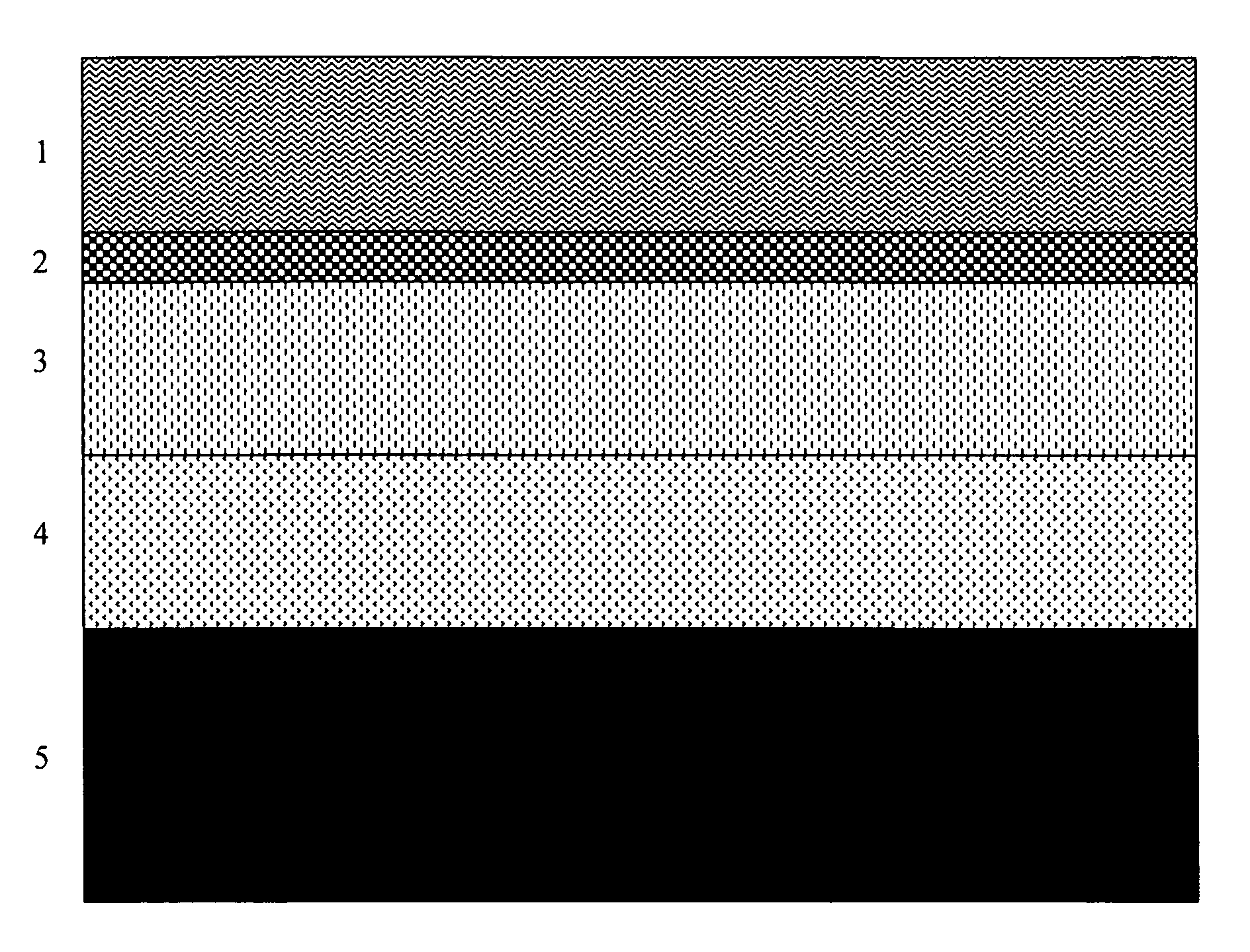
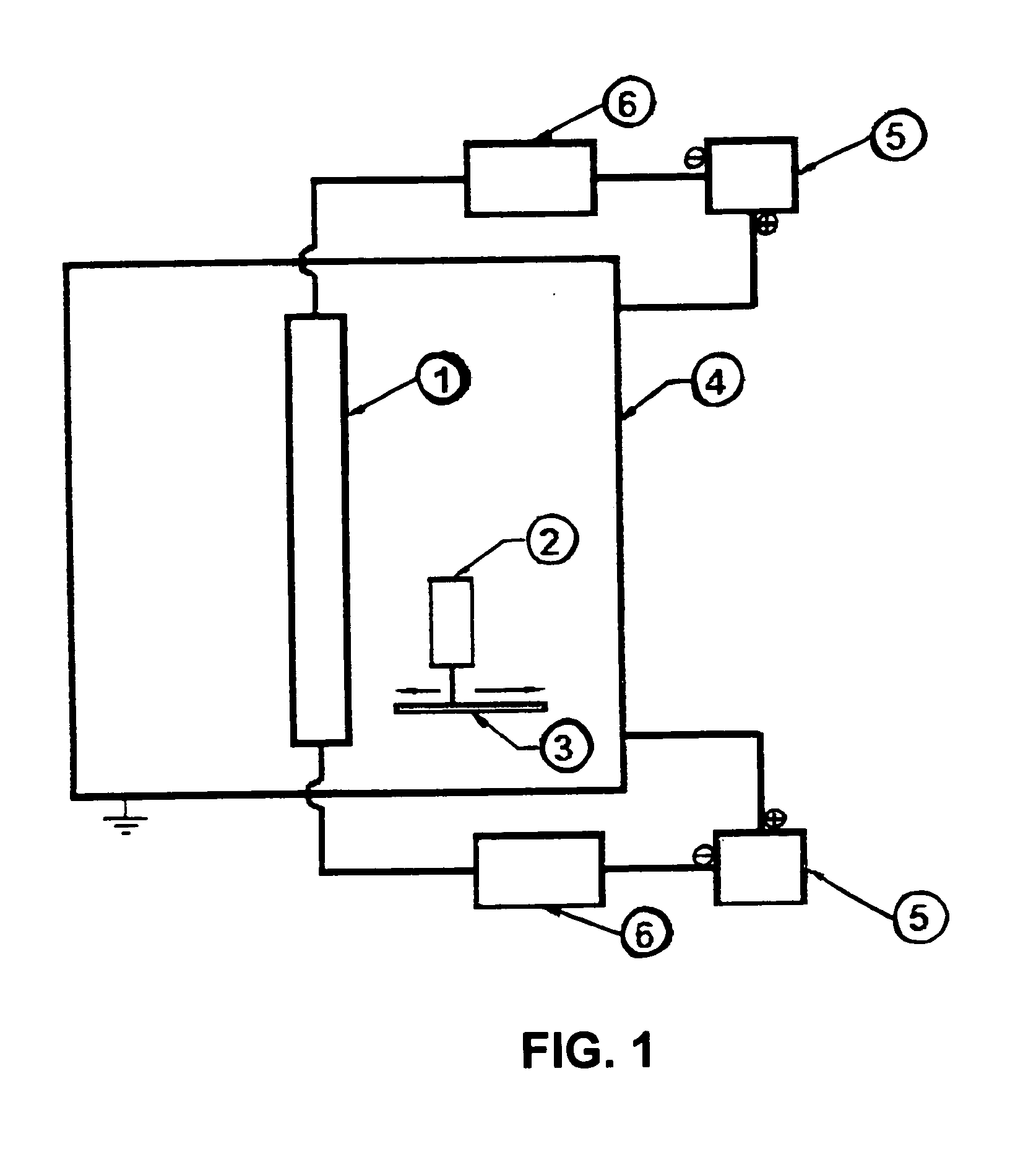
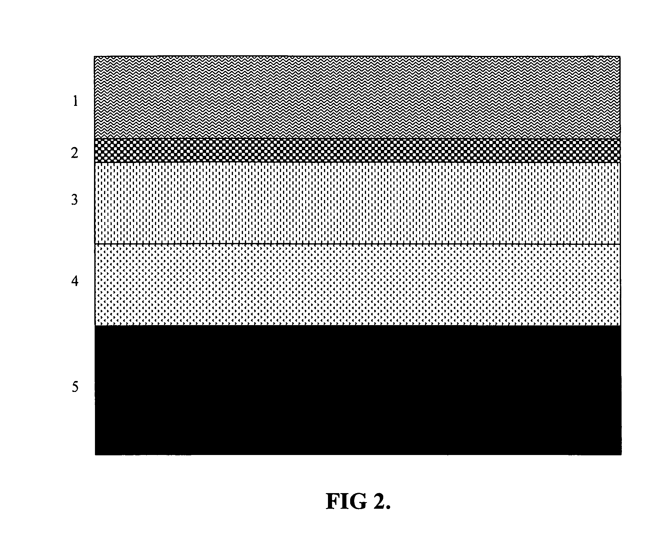
[0067]Ionic Plasma Deposition (IPD) utilizes a modified controlled vacuum arc discharge on a target material to create highly energized plasma. IPD differs from normal ion plasma depositions in several ways, including control of substrate distance from the target and precise control of arc speed. Arc control allows for faster movement, creating fewer macro particles without the use of sensors or filters. Slower movement deposits more macro particles leading to a rougher surface. Adjusting substrate distance from the target during deposition also controls density and size of the macro particles deposited.

[0068]A typical apparatus for using the modified IPD method is shown in FIG. 1. Deposition conditions are adjusted to the size and type of substrate, the target material, which for the examples shown is chrome or a chrome alloy. The substrate, which can be aluminum or steel as illustrated in the examples, is placed at a distance from the target so that...

example 2

Chrome Coated ABS Plastic

[0069]A solution of an ultraviolet curable polymer was flooded over the surface of an ABS plastic part at a thickness of ten microns and pre-cured for 120 sec. with radiant heat at 100° C. The part was then placed under a UVB light for eight min until fully cured. 99.99% chrome was deposited by the IPD method with IPD control at 300 Hz in accordance with the method of example 1 to a depth of 500 nm. An epoxyacrylate polymer was then coated to a thickness of 2 microns followed by curing for 120 sec. at a temperature of 100° C.

[0070]The quality of the coating met or exceeded the following standards: AST B-117 (salt spray); ASTM D-3359 (adhesion by reverse saw cut); ASTM D-3363 (hardness using gravelomener); and GM 264M (thermal cycling −30° C. to +85° C.)

example 3

Chrome Coated Hardened Steel or Aluminum

[0071]A hardened steel automotive wheel with major surface roughness was cleaned with phosphate solution followed by electrodeposition of an organic polymer to a thickness of 5 microns. A solution of an ultraviolet curable organic polymer was deposited by flood coat at a thickness of 10 microns and pre-cured for 120 sec with radiant heat at 100° C. The part was then placed under a UVB light for eight minutes until fully cured. A 99.995% chrome coating was deposited by the IPD method of example 1 controlled at 300 Hz to a thickness of 500 microns. A solution of an ultraviolet curable organic polymer coating was deposited by flood coating to a thickness of 2 microns and pre-cured with radiant heat for 120 sec at 100° C. The part was then placed under a UVB light for eight min until fully cured.

[0072]The analogous procedure was used to coat an aluminum substrate.

[0073]The quality of the coating on either the hardened steel or aluminum met or exce...


PUM

PropertyMeasurementUnit
thickaaaaaaaaaa
thickaaaaaaaaaa
thickaaaaaaaaaa

Abstract

A plasma vapor deposition method for producing highly reflective and adherent metal or metal alloy decorative coatings on articles such as automotive fixtures is described. The improved coatings are particularly applicable to chrome based coatings on automobile fixtures and accessories, including wheels, hubcaps, bumpers and door handles. The method also provides plated metal coatings such as gold, platinum and silver for jewelry and industrial tools.

Description

[0001]This application claims benefit of U.S. Provisional Application Ser. No. 60 / 779,122 filed Mar. 3, 2006, which is incorporated by reference in its entirety.BACKGROUND OF THE INVENTION[0002]1. Field of the Invention[0003]The invention relates to ionic plasma deposition methods for preparing highly reflective coatings substrate surfaces and more particularly to highly adherent chrome coatings on metal and plastic surfaces.[0004]2. Description of Background Art[0005]Currently employed methods for chrome plating are generally limited to electrodeposition and vacuum metallization. While chrome and chrome-based metals are highly desirable as a decorative finish, particularly for automotive vehicles, the coatings are expensive to produce and are subject to delamination and poor adhesion.[0006]Chrome plating is typically applied to metal substrates such as wheels and hubcaps using electroplating methods. The process requires first cleaning the wheels in order to provide a homogeneous s...

Claims


Application Information

Patent Timeline
Patent Type & Authority Applications(United States)
IPC IPC(8): G11B5/64B32B17/10B05D1/36C08F2/46H05H1/24
CPCB05D1/007B05D3/067B05D5/068C09D5/44C23C14/20Y10T428/265C23C14/54C23C14/584Y10T428/31Y10T428/266C23C14/325Y10T428/31678
Inventor STOREY, DANIEL M.
Owner METASCAPE
Why Eureka
Try Eureka