
Process For Producing Aluminum Nitride Crystal And Aluminum Nitride Crystal Obtained Thereby

a technology of aluminum nitride crystals and nitride crystals, which is applied in the direction of crystal growth process, polycrystalline material growth, gel state, etc., can solve the problems of unfavorable quality, unfavorable pressure and temperature applied to crystal growth, and the inability to produce crystals of bulk size that can be used as substrates, etc., to achieve mild production conditions, reduce corrosivity, and reduce the effect of pressure and temperatur

Inactive Publication Date: 2008-01-10
OSAKA UNIV +1
View PDF0 Cites 44 Cited by
  • Summary
  • Abstract
  • Description
  • Claims
  • Application Information

AI Technical Summary

Benefits of technology

[0009] As described above, a production method of the present invention is characterized by using a flux containing the component (A) and the component (B) or a flux containing the component (B) in liquid phase growth of aluminum nitride crystals using a flux. Accordingly, in the production method of present invention, the pressure and temperature applied for crystal growth can be lower than in conventional techniques so as to realize mild production conditions. A flux used in the present invention has lower corrosivity than those used in the conventional techniques, and therefore materials of equipment or apparatuses used in production have fewer restrictions than in conventional techniques. With a production method of the present invention, it is possible to obtain large aluminum nitride crystals of high quality and a bulk size, with fewer dislocations.

Problems solved by technology

However, it has been practically impossible with conventional production methods to produce a high-quality aluminum nitride crystal of a large size that can serve as a substrate.
However, it has been impossible with the sublimation method to produce crystals of a bulk size that can be used as a substrate.
Moreover, the obtained crystals included many dislocations, which caused unfavorable quality.
However, in this method, the melting point of the Ca3N2 flux is as high as 1,200° C. and prevention of degradation further is required, so that a severe condition under a high temperature and a high pressure is required.
In addition, due to the high corrosivity of the Ca3N2 flux, materials of equipment and apparatuses used, particularly materials to be used for a crucible, are limited.
Therefore, this method has difficulties in its commercialization due to severely restricted production conditions.

Method used


Image

  • Process For Producing Aluminum Nitride Crystal And Aluminum Nitride Crystal Obtained Thereby
  • Process For Producing Aluminum Nitride Crystal And Aluminum Nitride Crystal Obtained Thereby
  • Process For Producing Aluminum Nitride Crystal And Aluminum Nitride Crystal Obtained Thereby

Examples


example 1

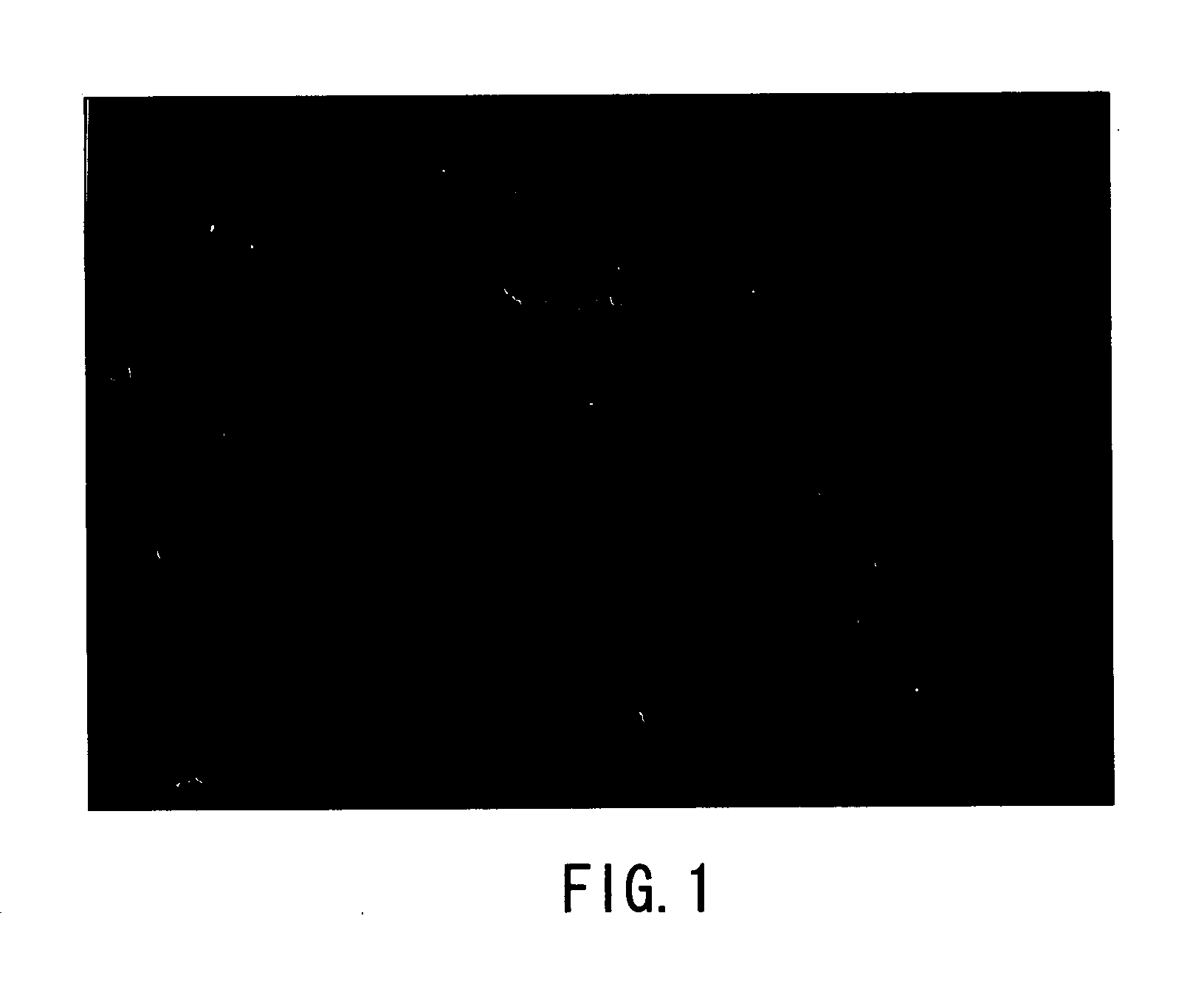
[0094] Aluminum nitride crystals were produced as described above, using the apparatuses shown in FIGS. 11A and 11B. Specifically, Al (raw material of crystal), Li (the component (A)) and In (the component (B)) were put in a BN crucible, and melted by applying heat and pressure under the conditions described below in an atmosphere of nitrogen (N2) gas so as to grow aluminum nitride crystals. Then, the obtained product was identified as the aluminum nitride crystal with an optical microscope and through X-ray diffraction measurement (XRD measurement). The optical micrograph (magnification: 100 times) of FIG. 1 shows the obtained aluminum nitride crystal (grown at Li:In=75:25).

[0095] (Production condition)

[0096] Growth temperature: 800° C.

[0097] Growth pressure: 30 atm (3.04 MPa)

[0098] Growth time: 96 hours

[0099] Crucible used: BN crucible (inner diameter of 9 mm)

[0100] Gas used: N2 gas

[0101] Al: 0.2 g

[0102] Al:flux (mole ratio)=3:7

[0103] Li:In (mole ratio)=50:50 and 75:25

example 2

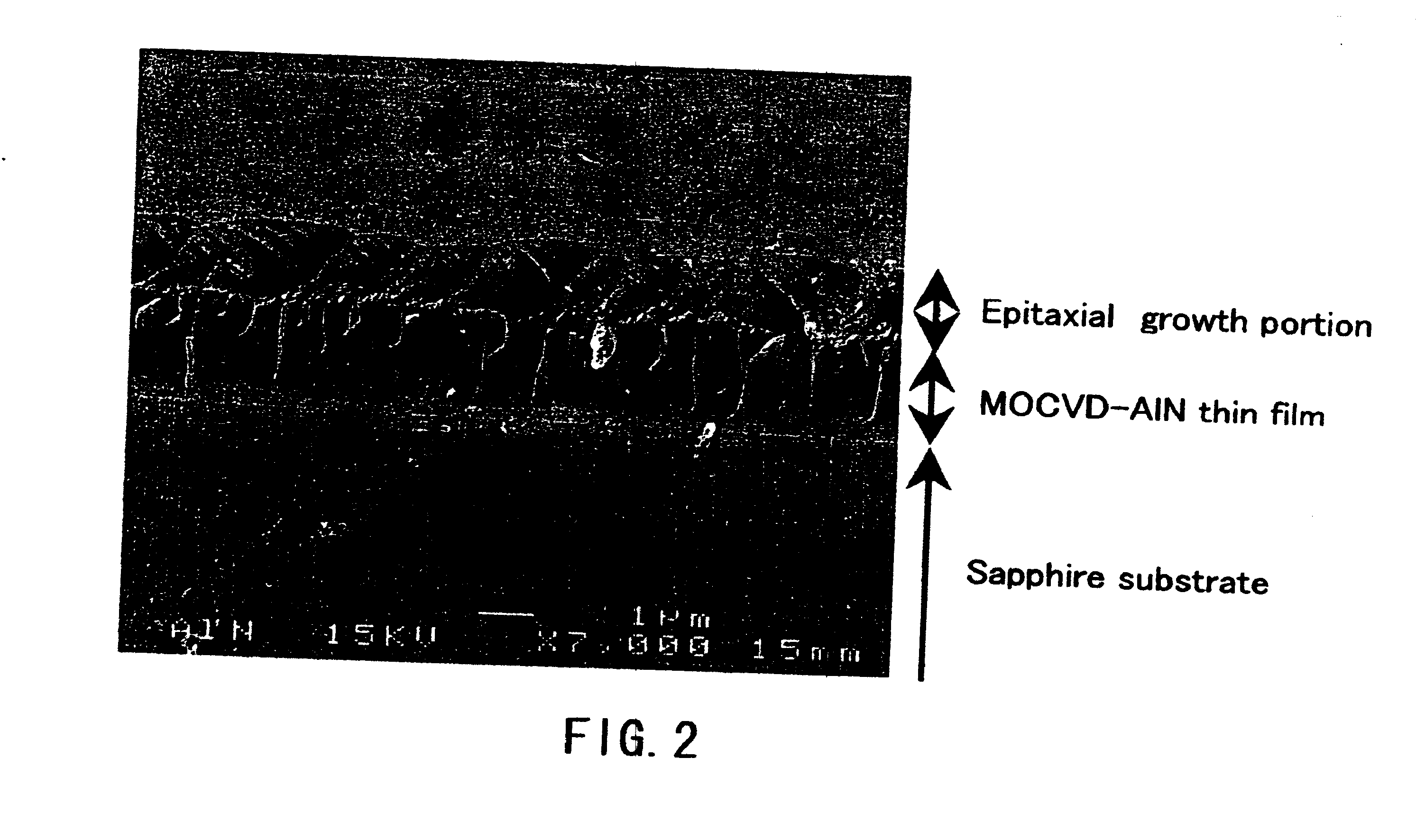
[0104] Aluminum nitride crystals were produced on a substrate disposed in a crucible using the apparatuses shown in FIGS. 11A and 11B. Specifically, Al (raw material of crystal), Na and Ca (the component (A)) and Sn (the component (B)) were put in a crucible having a substrate disposed therein, and melted by applying heat and pressure under the conditions described below in an atmosphere of nitrogen (N2) gas so as to grow aluminum nitride crystals. Then, the obtained product was identified as the aluminum nitride crystal with a scanning electron microscope (SEM) and through X-ray diffraction measurement (XRD measurement). The scanning electron micrograph (magnification: 7,000 times) of FIG. 2 shows the obtained aluminum nitride crystal. As shown in the micrograph of FIG. 2, in this example, it was observed that a transparent and flat thin film of aluminum nitride crystal with a thickness of approximately 1 μm had grown on a MOCVD-AlN thin film substrate. Note that “sapphire substrat...

example 3

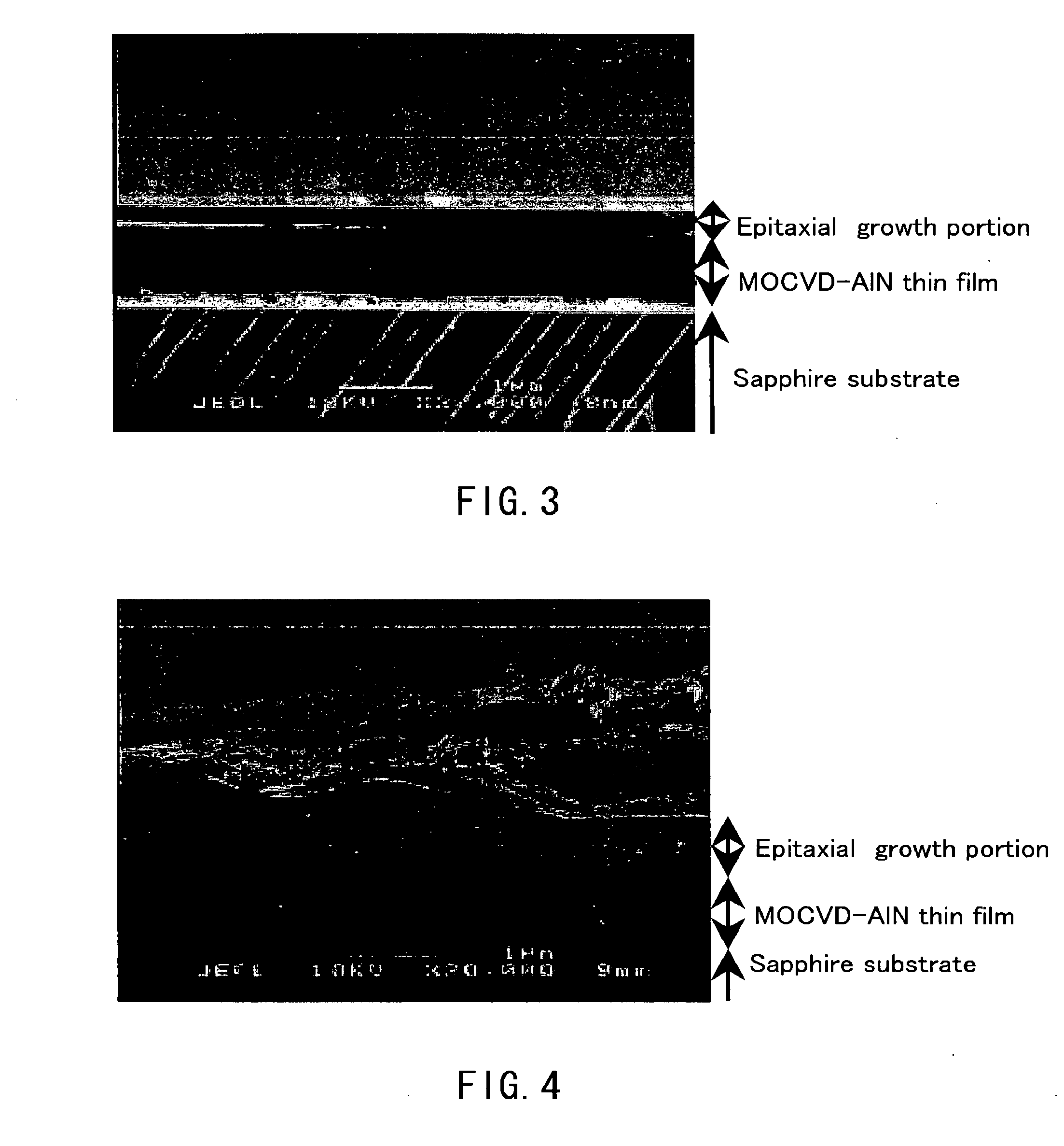
[0113] Aluminum nitride crystals were produced on a substrate disposed in a crucible using the apparatuses shown in FIGS. 11A and 11B. Specifically, Al (raw material of crystal) and Sn (the component (B)) were put in a crucible having a substrate disposed therein, and melted by applying heat and pressure under the conditions described below in an atmosphere of nitrogen (N2) gas so as to grow aluminum nitride crystals. Then, the obtained product was identified as the aluminum nitride crystal with a scanning electron microscope (SEM) and through X-ray diffraction measurement (XRD measurement). The scanning electron micrograph (magnification: 20,000 times) of FIG. 3 shows the obtained aluminum nitride crystal. As shown in the micrograph of FIG. 3, in this example, it was observed that a transparent and flat thin film of aluminum nitride crystal with a thickness of approximately 200 nm had grown on a MOCVD-AlN thin film substrate. Note that “sapphire substrate” in FIG. 3 indicates a sap...


PUM


Abstract

The present invention provides a method for producing aluminum nitride crystals under mild pressure and temperature conditions. In the production method of aluminum nitride crystals, aluminum nitride crystals are formed and grown in the presence of nitrogen-containing gas by allowing aluminum and the nitrogen to react with each other in a flux containing the following component (A) and component (B), or a flux containing the following component (B). (A) At least one element selected from the group consisting of the alkali metal and the alkaline-earth metal. (B) At least one element selected from the group consisting of tin (Sn), gallium (Ga), indium (In), bismuth (Bi) and mercury (Hg).

Description

TECHNICAL FIELD [0001] The present invention relates to methods for producing aluminum nitride crystals and aluminum nitride crystals obtained thereby. BACKGROUND ART [0002] Group-III nitride semiconductors are used in the fields of, for example, hetero-junction high speed electron devices and photoelectron devices (such as semiconductor laser, light-emitting diodes, sensors, etc.), and such use is expected to spread further in the future. Of Group-III nitride semiconductors, aluminum nitride (AWN) has a significantly large band gap of approximately 6.3 eV, and has high insulation properties. For this reason, aluminum nitride crystals are used for, for example, a barrier layer when using gallium nitride (GaN) as a light-emitting device. On the other hand, a more efficient excitation light source, specifically, an ultraviolet light source having a wavelength shorter than the band gap wavelength of gallium nitride, has been desired. In response to this, in order to obtain excitation l...

Claims


Application Information

Patent Timeline
IPC IPC(8): C01B21/072C30B29/38C30B9/10
CPCC30B9/00C30B29/403C30B9/10
Inventor MORI, YUSUKESASAKI, TAKATAMOKAWAMURA, FUMIOMASASHI, YOSHIMURAKAWAHARA, MINORUISOBE, HIROAKI
Owner OSAKA UNIV
Learn More