
Transition metal complex compound

a technology of complex compound and metal, applied in the field of transition metal complex compound, can solve the problems of short device life, weak bonding, marked poor heat resistance, and inability to describe the specific effect of a group bonded to an oxygen atom, and achieve the effect of high luminous efficiency

Inactive Publication Date: 2008-09-25
IDEMITSU KOSAN CO LTD +1
View PDF2 Cites 406 Cited by
  • Summary
  • Abstract
  • Description
  • Claims
  • Application Information

AI Technical Summary

Benefits of technology

[0018]The transition metal compound of the present invention having a metal carbene bond has an electroluminescent characteristic and can provide an organic EL device having a high luminous efficiency. Further, according to the production process of the present invention for a transition metal complex compound, the transition metal complex compound can efficiently be produced.

Problems solved by technology

However, they have a very short device life.
In particular, skeleton structures of ligands in which Ir metal is bonded to a phosphorus atom are described in the patent document 5 and the patent document 6, and while they emit blued light, they have weak bonding and are markedly poor in a heat resistance.
However, a specific effect of a group bonded to an oxygen atom is not described and uncertain.
Further, synthesis of iridium complexes having a carbene bond, an emission wavelength thereof and the performances of the device are described in the patent document 9, but the energy efficiency and the external quantum efficiency are low.
In addition thereto, the emission wavelength is distributed in a ultraviolet area, and the visual efficiency is inferior.
Accordingly, they are not suited to light emitting devices in a visual wavelength region such as organic EL.
They can not be vacuum-deposited because of a low decomposition temperature and a high molecular weight, and the complexes are decomposed in deposition, so that a problem is involved in the point that impurities are mixed in producing the devices.

Method used


Image

  • Transition metal complex compound
  • Transition metal complex compound
  • Transition metal complex compound

Examples


example 1

Synthesis of Transition Metal Complex Compound 1

(i) Synthesis of Compound a

[0165]A compound a was synthesized by the following reaction step according to a method described in a reference document (Chem. Pharm. Bull., 1965, 13, 1135):

[0166]2-Pyridinemethanol 25.6 g (0.239 mole), aniline 20.3 ml (0.214 mole) and potassium hydroxide 1.92 g (0.0341 mole) were heated and stirred in a Kjeldahl flask at 150° C. for 12 hours. As a result thereof, the solution was changed from a pale yellow oily state to a pale yellow suspension state. This was cooled down to room temperature, and 200 ml of water was added, followed by neutralizing the solution to pH 7 to 8 by diluted hydrochloric acid. Next, 500 ml of methylene chloride was added to this reaction solution, and an organic layer was extracted by means of a separating funnel. Further, the solution was extracted four times with 100 ml of methylene chloride. This solution was dehydrated on potassium carbonate, and a solid component was filtered...

example 2

Synthesis of Transition Metal Complex Compound 1

(i) Synthesis of Compound e

[0186]A compound e was synthesized according to the following reaction step:

[0187]Toluene 50 ml, 2-pyridinecarboxyaldehyde 9.55 ml (0.100 mole, 1.0 eq) and aniline 9.13 ml (0.100 mole, 1.0 eq) were put in a Kjeldahl flask, and as soon as stirring was started, a pale yellow solid matter was produced. Stirring was further continued, and all the solid matter was dissolved to obtain a colorless solution. After stirred at room temperature for 24 hours, the solvent was distilled off under reduced pressure to obtain quantitatively a pale yellow oily compound e. The measuring result of 1H-NMR is shown below.

[0188]1H-NMR (solvent: CDCl3, internal reference: TMS 0.00 ppm, 300 MHz, temperature: 35° C.): δ 7.28 to 7.45 (m, 5H, HPh), 7.37 (ddd, J=7.7, 4.7, 1.1 Hz, 1H, Hb), 7.82 (ddd, J=7.7, 7.7, 1.9 Hz, 1H, Hc), 8.21 (dd, J=7.7, 1.9 Hz, 1H, Hd), 8.62 (s, 1H, He), 8.72 (dd, J=7.7, 1.1 Hz, 1H, Ha)

(ii) Synthesis of Compound ...

example 3

Synthesis of Transition Metal Complex Compound 1

[0206]The compound 1 was synthesized according to the following reaction step:

[0207]The compound f 123 mg (0.100 mmole), silver oxide (I) (Ag2O (I)) 278 mg (1.20 mmole), the compound c 50.7 mg (0.220 mmole) and tetrahydrofuran (THF, deaerated solvent) 20 ml were put in a Schlenk bottle under argon atmosphere, and it was shielded from light with an aluminum foil and stirred under refluxing for 24 hours. The solvent component was distilled off from the reaction solution under reduced pressure, and this was refined by column chromatography using a deaerated solvent (CH2Cl2:hexane=2:1). As a result thereof, 82.1 mg (0.114 mmol, yield: 57.0%) of a pale yellow solid matter.

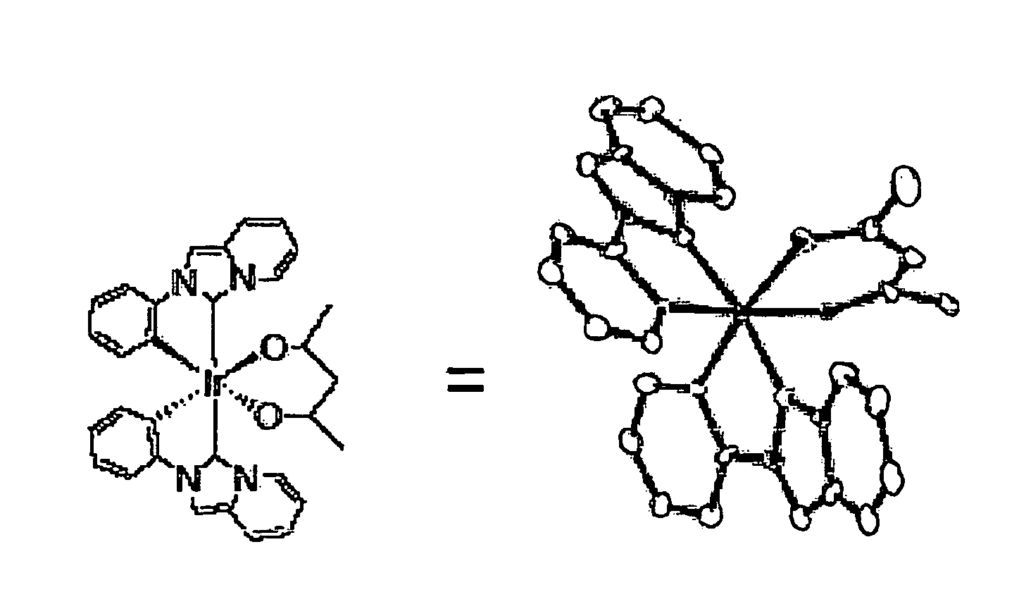
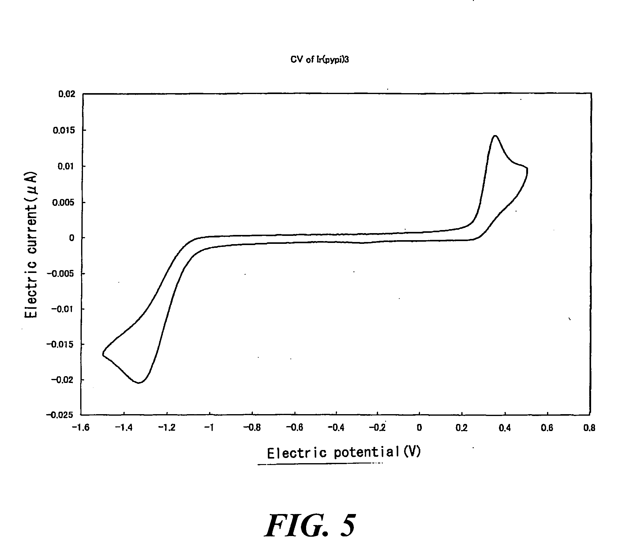
[0208]The result (refer to FIG. 5) of cyclic voltammetry and the result (refer to FIG. 6) of X-ray crystal structure analysis are shown below.

[Measuring Result of FAB-MS]

[0209]MS (FAB+): m / z=722 (M+), 579 (M+-(Ligand))

[Measuring result of cyclic voltammetry (vs Ag+ / Ag in C...


PUM

PropertyMeasurementUnit
Electroluminescenceaaaaaaaaaa
Luminous efficiencyaaaaaaaaaa
Luminescenceaaaaaaaaaa

Abstract

The present invention provides a transition metal complex compound of a specific structure having a metal carbene bond, a production process for the same and an organic EL device in which an organic thin film layer comprising a single layer or plural layers having at least a luminescent layer is interposed between an anode and a cathode, wherein at least one layer in the above organic thin film layers contains the transition metal complex compound having a metal carbene bond described above. Provided are a novel transition metal complex compound having a metal carbene bond which has an electroluminescent characteristic and which can provide an organic electroluminescent device having a high luminous efficiency and a production process for a transition metal complex compound.

Description

BACKGROUND OF THE INVENTION[0001]The present invention relates to a transition metal complex compound, specifically to a transition metal complex compound having an electroluminescent characteristic which can provide an organic electroluminescent device having a high luminous efficiency and a production process for the transition metal complex compound.RELATED ART[0002]An organic electroluminescent (EL) device is a spontaneous luminescent device making use of the principle that a fluorescent substance emits light by recombination energy of holes injected from an anode and electrons injected from a cathode by applying an electric field. Since a low voltage-driven organic EL device of a laminate type was reported by C. W. Tang et al. of Eastman Kodak Company (C. W. Tang and S. A. Vanslyke, Applied Physics Letters, Vol. 51, p. 913, 1987), researches on organic EL devices comprising organic materials as structural materials have actively been carried out. Tang et al. use tris(8-hydroxyq...

Claims


Application Information

Patent Timeline
IPC IPC(8): B32B9/00C07F15/00
CPCC07F15/0033Y10T428/31678
Inventor MASHIMA, KAZUSHIWATANABE, MASAMI
Owner IDEMITSU KOSAN CO LTD
Learn More