Polymeric Nanopillars and Nanotubes, Their Manufacture and Uses

Active Publication Date: 2010-05-06
BOARD OF SUPERVISORS OF LOUISIANA STATE UNIV & AGRI & MECHANICAL COLLEGE
View PDF5 Cites 21 Cited by
  • Summary
  • Abstract
  • Description
  • Claims
  • Application Information

AI Technical Summary

Benefits of technology

[0062]In initial tests on early prototypes, we observed that the PUHARNs were shorter in length than the nanochannels of the AAO replication templates. Without wishing to be bound by this hypothesis, we attributed the difference to gases trapped in the nanochannels. We used ultrasonication to degas the channels during fabrication of nanopillars, followed by high vacuum to degas the AAO nanopores. This treatment practically eliminated back pressure when the liquids subsequently wetted and flowed into the channels, resulting in PUHARNs of the expected lengths, without significant shortening.
[0063]In other initial tests, we had observed that after the AAO was removed with aqueous NaOH and then air dried following the methods described in prior reports on fabricating CdS nanowires, block copolymer nanotubes, and metallic nanotubes (e.g., W. Lee et al., Langmuir 2004, 20, 7665-7669; H. Xiang et al., Macromolecules 2004, 37, 5660-5664; Y. Liang et al., J. Am. Chem. Soc. 2004, 126, 16338-16339; W. Lee, Angew. Chem. Int. Ed. 2005, 44, 6050-6054), the polymeric high-aspect-ratio nanopillars/nanotubes routinely collapsed into an entangled mesh or clusters. SEM images of such samples demonstrated that PMMA nanopillars collapsed, and nanotubes congregated into 1-2 μm bundles clustered into disordered domains. Without wishing to be bound by this hypothesis, we attributed the observed collapse to surface tension forces acting on the nanopillars/nanotubes during the evaporation of the rinse liquid. On the scale of the nanopillars or nanotubes, the force due to surface tension is considerable. Modeling a nanostructure as a lever, the force F acting on a nanostructure in contact with an evaporating rinse liquid of given surface tension γ is proportional to the pillar or tube's aspect ratio A, inversely proportional to the interpillar spacing d, and proportional to the cosine of the contact angle θ of the rinse liquid at the nanopillar/nanotube surface: FαAγ(cos θ)/d. To reduce this force, the surface tension could be reduced, or the contact angle of the rinse liquid with respect to the nanostructures could be brought close to 90° (cos θ=0). We have discovered that the latter can be accomplished by simple freeze-drying removal at −80° C. of the liquid in contact with the PUHARNs, instead of supercritical drying. The surface tension drops essentially to zero as the liquid freezes, avoiding problems from surface tension effects. Either freeze-drying or supercritical drying may be used to remove the solvent. Supercritical dry

Problems solved by technology

Although 2-D gel electrophoresis can resolve more than 1,000 proteins in a single analysis, it has significant limitations.
First, its resolving power may be orders of magnitude too small for proteomics, because the sheer number of distinct proteins present in a sample could be on the order of 1,000,000.
Further complexity arises from the numerous interactions that occur among proteins, and between proteins and other ligands.
Current bench top electrophoresis methods can be subject to run-to-run reproducibility problems, which can make it difficult to resolve or compare differences between two different gels, whether or the same or different specimens.
A typical analysis involves several time-consuming, labor-intensive, skilled operations.
Another challenge in protein separation is that the concentrations of different proteins can vary enormously, sometimes by up to ten orders of magnitude.
The stains have differing sensitivities to protein structures and concentrations, and are not reliably quantitative.
Because of the difficulties and limita

Method used


Image

  • Polymeric Nanopillars and Nanotubes, Their Manufacture and Uses
  • Polymeric Nanopillars and Nanotubes, Their Manufacture and Uses
  • Polymeric Nanopillars and Nanotubes, Their Manufacture and Uses

Examples


Example

Example 1

Integrated Protein Analysis System Overview

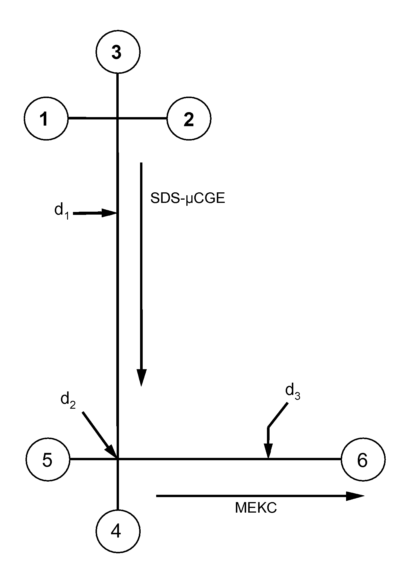
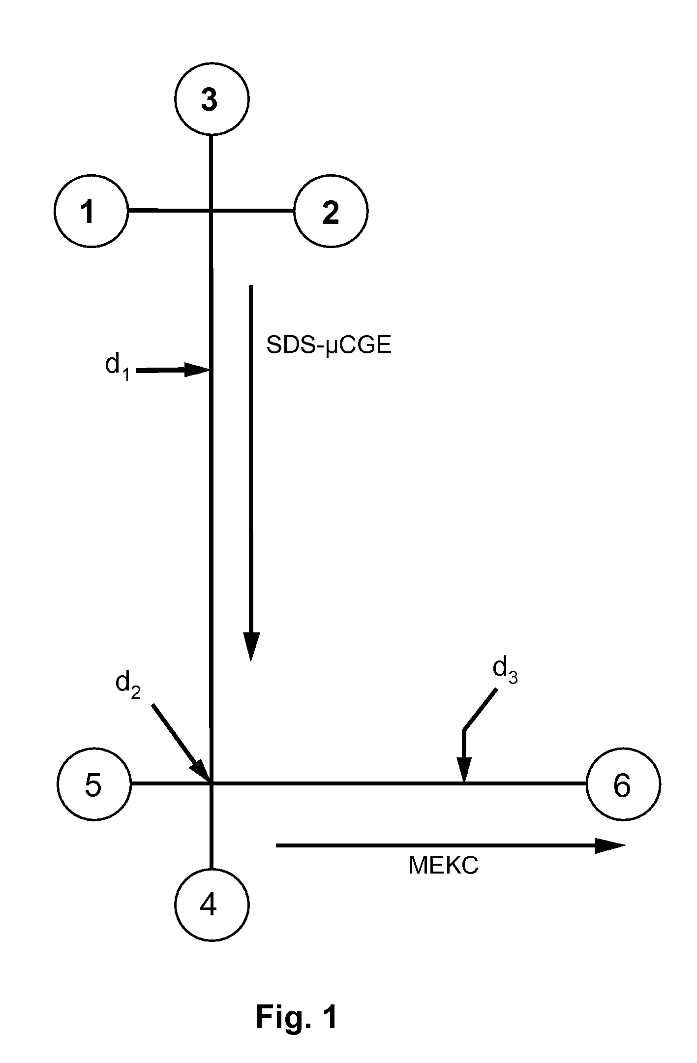
[0055]There is an unfilled need for a unitary system for profiling proteins, a system in which the processing steps are seamlessly integrated, and whose output may be interfaced to a mass spectrometer or other analytic instrument. One embodiment of the invention employs the novel nanoarrays in an integrated microfluidic system that can select a sub-population of proteins from whole cell lysates and process these proteins directly on-chip, in a fully automated fashion, much faster than previous state-of-the-art systems have been able to achieve. A prototype embodiment of such a system has been fabricated via micro-replication technologies in PMMA. PMMA was chosen since its surface may readily be modified chemically, and since it has shown excellent performance in a variety of micro-separation formats. A schematic of the integrated system is shown in FIG. 10. In a preferred embodiment the system includes subunits for the selective ca...

Example

Example 2

Fabrication of Polymeric Nanopillars

[0060]The fabrication process is illustrated schematically in FIG. 5. Anodized aluminum oxide (AAO) templates were prepared via a two-step anodization process. The AAO templates comprised an Al substrate with an AAO layer having nanochannels open on one end. Methyl methacrylate (MMA) monomer (Fisher Scientific, Pittsburgh, Pa.) containing 1% w / v benzoin methyl ether (Fisher Scientific, Pittsburgh, Pa.), and 1% w / v PMMA (Mw 93,300 and Mn 46,400; Scientific Polymer Products Inc., Ontario, N.Y.; CAT#037Sb) was introduced into the nanochannels of the AAO templates by ultrasonicating (Branson Ultrasonic Cleaner Model 2510) the template and the methyl methacrylate / benzoin methyl ether / MMA solution for 30 min. The sample was then immediately placed on a glass support, either under laboratory ambient atmosphere or under N2, and polymerization was induced by a 30-min exposure to 254-nm UV (15 mW / cm2, DUV Exposure System, ABM, Inc., San Jose, Calif...

Example

Example 3

Preparation of Polymer Nanotubes

[0061]The AAO template was prepared by a two-step anodization process, followed by removal of the Al support with saturated aqueous mercuric chloride for 5-24 h. Subsequent dissolution of the oxide barrier-layer with 6% wt. H3PO4 at 40° C. for 30 min yielded AAO templates possessing nanochannels with both ends open. A piece of 0.25-mm thick polymer sheet, either PMMA (Goodfellow, Devon, Pa.) or COC (Topas 6013D61 Advanced Polymers GmbH, Florence, Ky.), was placed in contact with the anodic aluminum oxide surface. The assembly was then clamped together between two glass microscope slides using binding clips (ACCO, Lincolnshire, Ill.). The polymer was melted by heating at 230° C. for 10 min under vacuum (170 Pa) in a standard vacuum oven. The polymer / AAO composite was then cooled to room temperature and removed from the glass slide support by soaking the assembly in an ultrasonic water bath. The AAO template pattern was dissolved in 0.6 M H3PO4...


PUM

PropertyMeasurementUnit
Lengthaaaaaaaaaa
Diameteraaaaaaaaaa
Diameteraaaaaaaaaa

Abstract

A method is disclosed for fabricating free-standing polymeric nanopillars or nanotubes with remarkably high aspect ratios. The nanopillars and nanotubes may be used, for example, in integrated microfluidic systems for rapid, automated, high-capacity analysis or separation of complex protein mixtures or their enzyme digest products. One embodiment, preferably fabricated entirely from polymer substrates, comprises a cell lysis unit; a solid-phase extraction unit with free-standing, polymeric nanostructures; a multi-dimensional electrophoretic separation unit with high peak capacity; a solid-phase nanoreactor for the proteolytic digestion of isolated proteins; and a chromatographic unit for the separation of peptide fragments from the digestion of proteins. The nanopillars and nanotubes may also be used to increase surface area for reaction with a solid phase, for example, with immobilized enzymes or other catalysts within a microchannel, or as a solid support for capillary electrochromatography-based separations of proteins or peptides.

Description

[0001](In countries other than the United States:) The benefit of the 14 Sep. 2006 filing date of U.S. provisional patent application Ser. No. 60 / 844,506 is claimed under applicable treaties and conventions. (In the United States:) The benefit of the 14 Sep. 2006 filing date of U.S. provisional patent application Ser. No. 60 / 844,506 is claimed under 35 U.S.C. §119(e).[0002]The Development of this invention was partially funded by the United States Government under grants DBI-0138048 and EPS-0346411 awarded by the National Science Foundation. The United States Government has certain rights in this invention.TECHNICAL FIELD[0003]This invention pertains to polymeric nanopillars and nanotubes, their manufacture, and their uses in chemical and biological separations, analyses, and reactions.BACKGROUND ART[0004]The “proteome” is the complete set of proteins expressed by a cell or population of cells. “Proteomics” is the study of proteomes. An essential step in proteomics is the isolation ...

Claims


Application Information

Patent Timeline
IPC IPC(8): G01N27/26B82B3/00B32B5/16
CPCB81C1/00111Y10T428/2982G01N27/44773B81C2201/034
Inventor SOPER, STEVEN A.MCCARLEY, ROBIN L.CHEN, GUOFANGSHADPOUR, HAMED
Owner BOARD OF SUPERVISORS OF LOUISIANA STATE UNIV & AGRI & MECHANICAL COLLEGE
Why Eureka
Try Eureka