Composite Structures with Porous Anodic Oxide Layers and Methods of Fabrication

a technology of porous anodic oxide and composite structures, applied in the direction of membranes, superimposed coating processes, separation processes, etc., can solve the problems of reducing the hydrogen permeability of the membrane, reducing the effective life of the typical composite gas separation module having a hydrogen-selective metal membrane bonded to a porous substrate, and generally unsuitable polymer membranes. , to achieve the effect of reducing manufacturing costs, reducing manufacturing costs, and improving gas flux

Inactive Publication Date: 2010-06-03
WORCESTER POLYTECHNIC INSTITUTE
View PDF81 Cites 12 Cited by
  • Summary
  • Abstract
  • Description
  • Claims
  • Application Information

AI Technical Summary

Benefits of technology

[0021]In one embodiment, the intermediate porous metal layer has a smaller pore size than the porous metal substrate. Since the effective pore size of the support is made smaller, less hydrogen-selective metal can be used to form a dense hydrogen-selective membrane. Thus, a composite gas separation module having a dense hydrogen-selective membrane thinner than dense hydrogen-selective membranes of conventionally produced composite gas separation modules can be fabricated. Forming a thinner dense hydrogen-selective membrane can also simplify manufacturing by reducing the number of layers of hydrogen-selective metal that must be applied to the porous substrate to form a dense hydrogen-selective membrane. Therefore, practice of the present invention can reduce manufacturing costs, e.g., material, labor and capital costs, for fabricating composite gas separation modules as compared to conventional fabrication techniques.
[0022]Since thinner dense hydrogen-selective membranes typically produce higher rates of gas flux, composite gas separation modules fabricated as described herein can produce higher rates of gas flux, e.g., hydrogen flux. Thus, gas separation processes utilizing the composite gas separation modules described herein can achieve higher rates of gas separation than is possible using conventional composite gas separation modules employing thicker dense hydrogen-selective membranes.
[0023]Practice of the present invention can protect against diffusion of substrate components into a dense gas-selective membrane. By preventing or reducing the diffusion of substrate components into the dense gas-selective membrane, the gas permeation flux through the composite gas separation module can be maintained throughout operation of the composite gas-separation module in a gas separation process. In addition, the methods described herein for preventing or reducing the diffusion of substrate components into the dense gas-selective membrane are economical and relatively simple to perform.
[0024]The composite filters described herein can be useful for high stress applications and high temperature applications. Such filters should be useful for a range of applications such as for filtering nano-sized materials in high stress and high temperature environments. In particular, the described methods for fabricating composite filters are relatively simple and should be quite cost effective to perform.

Problems solved by technology

Where separations must be performed in conjunction with high-temperature processing, however, polymer membranes are generally unsuitable because they tend to thermally decompose.
The effective life of a typical composite gas separation module having a hydrogen-selective metal membrane bonded to a porous substrate often is limited by diffusion of substrate components into the membrane which decreases the hydrogen permeability of the membrane.
However, ceramic substrates are typically more brittle than predominantly metallic substrates.
Further, ceramic substrates can be more difficult to fabricate and also can be more difficult to join to other components in a gas separation system.
However, such a module can be very expensive to produce and can lack the mechanical strength that can be required for high pressure and / or high temperature applications.

Method used


Image

  • Composite Structures with Porous Anodic Oxide Layers and Methods of Fabrication
  • Composite Structures with Porous Anodic Oxide Layers and Methods of Fabrication
  • Composite Structures with Porous Anodic Oxide Layers and Methods of Fabrication

Examples


example 1

[0112]This example describes the preparation of thin aluminum layers bonded to metal substrate surfaces.

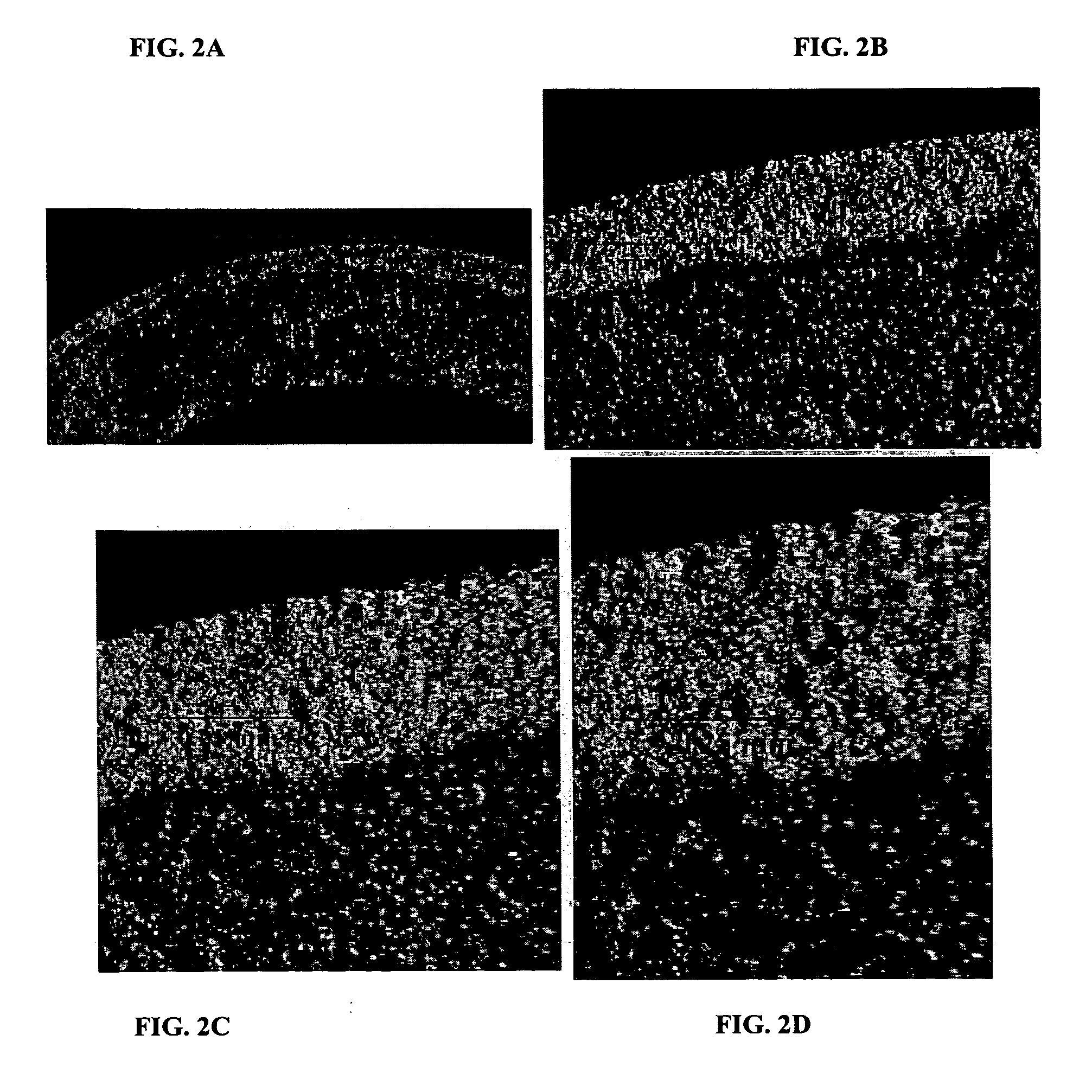
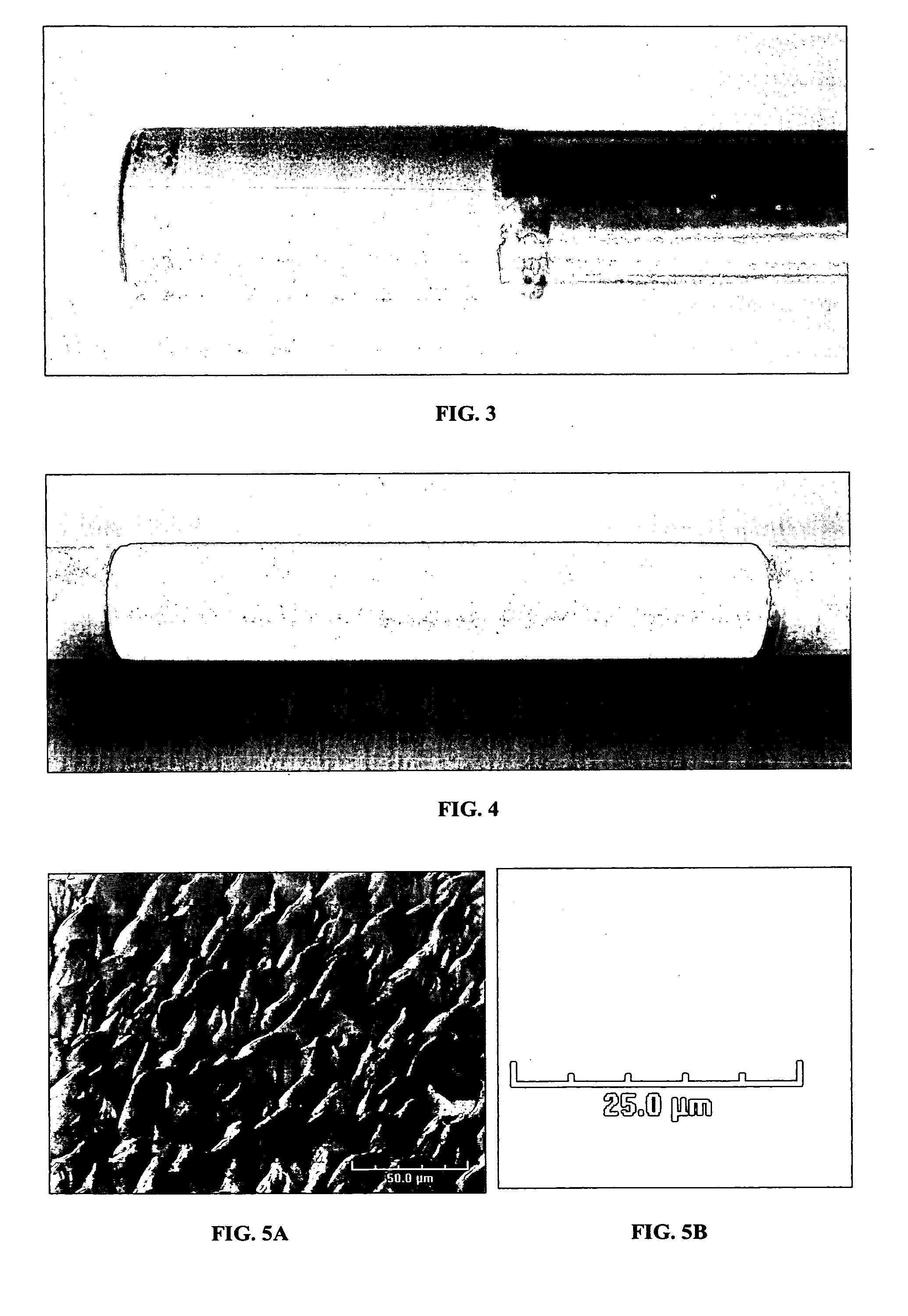
[0113]A bonded aluminum layer was formed by sputtering aluminum metal onto the outside surface of a 0.1 micron grade porous 316L stainless steel (“PSS”) substrate tube manufactured by Mott Metallurgical Corporation. FIGS. 2A to 2D are optical micrographs of a cross section of the PSS tube under various magnifications. FIG. 3 shows a 0.5 inch O.D. (outside diameter) PSS tube assembly having about 176 microns (determined gravimetrically) of aluminum metal sputtered onto a PSS tube (surface area 10 cm2).

[0114]A bonded aluminum layer was formed by sputtering aluminum metal onto the outside surface of a 0.1 micron grade porous INCONEL® substrate tube. FIG. 4 shows the 1.0 inch O.D. INCONEL® tube assembly that was made by sputtering aluminum metal onto the INCONEL® tube (surface area 120 cm2) for an aluminum thickness of 60 microns (determined gravimetrically).

example 2

[0115]This example describes formation of porous anodic aluminum oxide layers by anodic oxidation of aluminum surfaces.

[0116]The aluminum surface of an aluminum foil (5.5 cm2, 2 millimeters thick) was degreased in acetone and then ultrasonically cleaned. Next, the aluminum foil was rinsed in deionized (“DI”) water and etched in 3.0 mole / liter (mol / L) sodium hydroxide (NaOH) until bubbles occurred over the surface. The aluminum foil was then cleaned ultrasonically in DI water. The aluminum surface was then electropolished in a perchloric acid and ethanol mixture (70% HClO4 and C2H5OH at 1:3) at 20 volts (V) for 5 minutes. FIGS. 5A and 5B are SEM images of the aluminum surface before electropolishing (FIG. 5A) and after electropolishing (FIG. 5B). FIG. 6 is a photograph of an aluminized PSS tube (surface area 10 cm2) aluminized with 176 microns of metal as described in Example 1 after electropolishing.

[0117]Experiments were performed wherein an anodic aluminum layer was formed on a cl...

example 3

[0125]This example describes the formation of composite gas-separation module according to one embodiment of the present invention.

[0126]An aluminized 0.5 inch O.D. PSS tube assembly was used having a porous part length of about 1 inch and a gravimetrically estimated aluminum metal thickness of 176 microns. FIG. 3 is a picture of the assembly. The assembly was cleaned with acetone.

[0127]The aluminized PSS tube was electropolished using a four electrode configuration in a glass cylinder. The aluminum metal-coated PSS tube was used as the anode. Three 0.25 inch O.D. aluminum rod cathodes were symmetrically placed around the anode. The distances between the anode surface and the cathodes were approximately 0.375 inch. The electropolishing was carried out in a voltage range of 6.7-5.0 V DC for five minutes. The initial voltage on the electrodes without electrolyte solution was set at 20 V DC. The electrolyte solution used for the electropolishing was a mixture of 70% HClO4 and C2H5OH in...


PUM

PropertyMeasurementUnit
temperaturesaaaaaaaaaa
pressureaaaaaaaaaa
temperatureaaaaaaaaaa

Abstract

Composite structures are described that have a porous anodic oxide layer such as, for example, a porous anodic aluminum oxide layer. In one aspect, the present invention includes a composite gas separation module having a porous metal substrate; a porous anodic aluminum oxide layer, wherein the porous anodic aluminum oxide layer overlies the porous metal substrate; and a dense gas-selective membrane, wherein the dense gas-selective membrane overlies the porous anodic aluminum oxide layer. A composite filter is described having a porous non-aluminum metal substrate; and a porous anodic aluminum oxide layer, wherein the porous anodic aluminum oxide layer defines pores extending through the porous anodic aluminum oxide layer. Methods for fabricating composite gas separation modules and composite filters and methods for selectively separating hydrogen gas from a hydrogen gas-containing gaseous stream are also described.

Description

RELATED APPLICATION[0001]This application claims the benefit of U.S. Provisional Application No. 60 / 921,902, filed on Apr. 5, 2007. The entire teachings of the above application are incorporated herein by reference.BACKGROUND OF THE INVENTION[0002]Gas separation modules are commonly used to selectively separate a particular gas from a gas mixture. Two of the most common gas separation modules are polymer membranes and metallic composites. Polymer membranes can provide an effective and cost-efficient option for separating a gas at low temperatures. Where separations must be performed in conjunction with high-temperature processing, however, polymer membranes are generally unsuitable because they tend to thermally decompose.[0003]The development of high-temperature processing, along with tighter environmental regulations, requires utilization of gas separation modules that provide high flux, high selectivity of separation, and the ability to operate at elevated temperatures. Instead o...

Claims


Application Information

Patent Timeline
Patent Type & Authority Applications(United States)
IPC IPC(8): B01D53/22C23C28/04C23C28/00
CPCB01D53/228B01D2325/22B01D67/0065B01D67/0069B01D67/0072B01D69/04B01D69/10B01D69/12B01D71/022B01D71/025B01D2256/16C01B3/503C01B3/505C01B2203/0405C01B2203/041C01B2203/0475B01D2323/24B01D2325/02B01D67/0062
Inventor MA, YI HUAMARDILOVICH, IVAN P.
Owner WORCESTER POLYTECHNIC INSTITUTE
Why Eureka
Try Eureka