Substrate plasma treatment using magnetic mask device

a magnetic mask and substrate technology, applied in the direction of decorative surface effects, decorative arts, chemical vapor deposition coating, etc., can solve the problems of no accurate pattern being taken over from the mask device on the substrate, and none of the prior art publications described above disclose the use of the mask device positioned. , to achieve the effect of convenient and efficient treatment of flat surfaces and easy generation

Active Publication Date: 2010-06-17
FUJIFILM MFG EURO
View PDF41 Cites 13 Cited by
  • Summary
  • Abstract
  • Description
  • Claims
  • Application Information

AI Technical Summary

Benefits of technology

[0006]According to the present invention, a method according to the preamble defined above is provided, in which the method further comprises providing a magnetic layer on a surface of at least the first electrode in the treatment space, providing a substrate in contact with the magnetic layer, providing a mask device in contact with the substrate, the mask device interacting with the magnetic layer, and applying a plasma generating power to the first and second electrode for treatment of surface areas of the substrate exposed by the mask device (i.e. exposure of areas not covered by the mask device to the plasma in operation). The interaction between mask device and magnetic layer provides a close or intimate contact between the mask device and the substrate, i.e. there is basically no distance between the mask device and the substrate and if there would be a distance at all, the maximum distance between the mask device and the substrate is less than a predetermined distance, e.g. less than 1 micrometer, in order to prevent any air gaps. Without the application of a magnetic layer there might be a distance between the mask device and the substrate, as a result of which no accurate pattern will be taken over from the mask device on the substrate because of edge effects. The contact is furthermore plan-parallel, i.e. the maximum distance is achieved at any place over the entire substrate surface. In another embodiment the same provisions (mask device, substrate, magnetic layer foil) as applied on the first electrode are also applied to the second electrode. None of the prior art publications described above disclose the use of a mask device positioned on one of the electrodes of an atmospheric DBD system to pattern the substrate covered by the mask device. The present method allows to generate a bulk plasma in the treatment space at normal (low) breakdown voltages without any (structural) obstructions in the treatment space. The supply of reactive gasses (plasma) to the holes and gaps in the masking device near to the surface of the substrate is obtained by diffusion from the bulk plasma. The present method may also be applied to use the second electrode for treatment of a substrate, in which the second electrode is also provided with a magnetic layer, substrate and mask device.
[0007]The electrodes may be planar electrodes, which results in a rectangular treatment space, which allows easy and efficient treatment of flat surfaces of a substrate. The magnetic layer, substrate and mask device form a dielectric barrier on the first electrode, as a result of which the plasma discharge generated may be a very uniform plasma. In a further embodiment the plasma generated may be an atmospheric glow discharge plasma. Possibly, also the second electrode may be provided with a dielectric barrier, allowing to easier generate a uniform atmospheric pressure discharge plasma or glow discharge plasma in the treatment space.

Problems solved by technology

Without the application of a magnetic layer there might be a distance between the mask device and the substrate, as a result of which no accurate pattern will be taken over from the mask device on the substrate because of edge effects.
None of the prior art publications described above disclose the use of a mask device positioned on one of the electrodes of an atmospheric DBD system to pattern the substrate covered by the mask device.

Method used


Image

  • Substrate plasma treatment using magnetic mask device
  • Substrate plasma treatment using magnetic mask device
  • Substrate plasma treatment using magnetic mask device

Examples


example 1

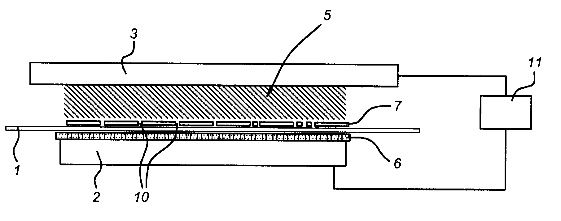
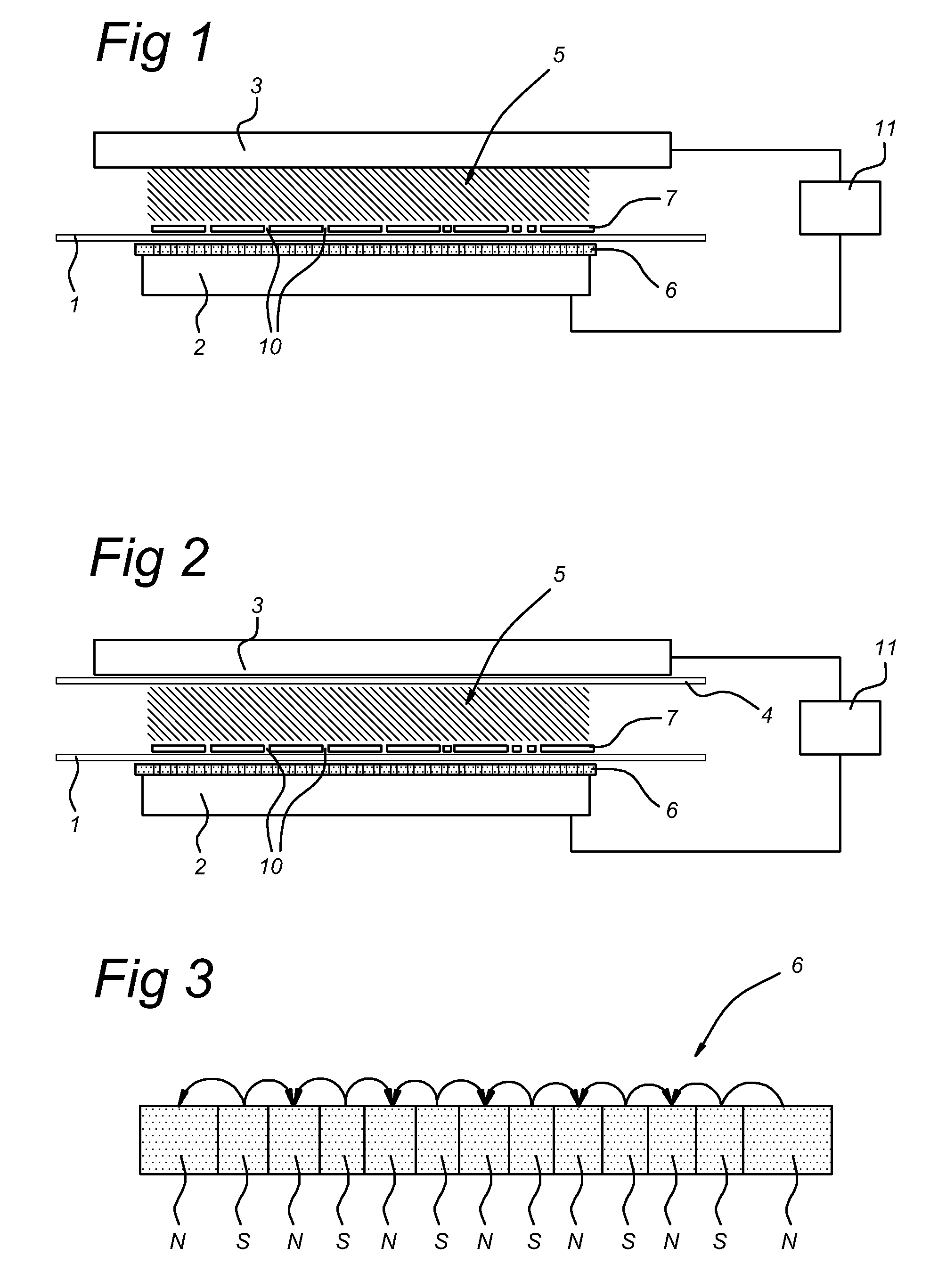
[0033]The present method and apparatus may be used for a localized activation of a hydrophobic substrate 1. A thin film of poly-ethylene (PE), is placed in the treatment space 5 of the apparatus of FIG. 1. An argon / nitrogen (5:1) mixture (first example) or an argon / oxygen mixture (5:0.1) (second example) is introduced in the treatment space 5, and a short plasma treatment of 10 seconds was applied (frequency 130 kHz, duty cycle 2% (i.e. the ratio between plasma on time and plasma off time), pulse on-time of 100 μsec). By controlling the displacement current and electrode distance, a glow discharge plasma is generated which result in a uniform activation of the (unmasked) surface parts. In the first case, mainly amine / amide-like groups are formed on the surface of the substrate 1, and in the second case mainly peroxy-, hydroxy- and carboxy-groups are formed. In both cases, the surface of the PE substrate 1 becomes hydrophilically patterned, which for example allows easy printing.

[003...

example 2

[0044]Localized etching of a substrate 1 of polymeric base material (including Si wafer, glass, inorganic coatings, etc.) may also be executed using the present method and apparatus embodiments. In this example, the substrate 1 is a PE film. Two different gas mixtures were used, i.e. an argon / oxygen (5:1) mixture and a argon / CF4 (5:0.1) mixture. Plasma treatment was carried out in a similar manner as in example 1, applying a total etching time of 60 seconds. After plasma exposure, the depth of trenches and wells in the substrate 1 was determined using a laser profilometer. In the case of argon / oxygen mixture, the etch rate was determined to be 500 nm / min, and in the case of the argon / CF4 mixture, the etch rate was 1 μm / min. The present invention may also be used to etch a pattern on the surface of the substrate 1, e.g. by using a gas mixture of Ar, CF4 and H2 in the treatment space 5. Areas on the substrate surface exposed to the plasma can be etched in order to generate small holes...

example 3

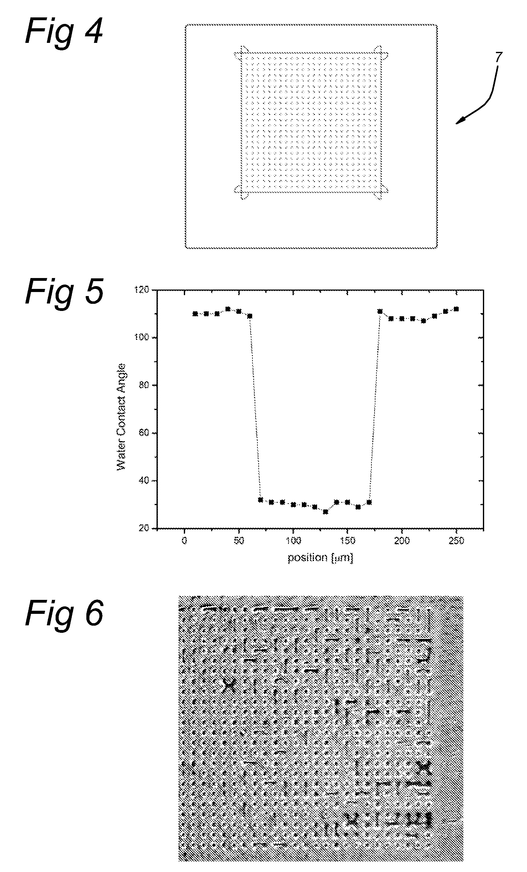
[0045]An ITO glass substrate 1 (0.7 mm thick) was spin coated with a hydrophobic photo resist of 1 μm thick. Again, argon / oxygen and argon / CF4 mixtures were used to locally etch the photo resist layer. After two minutes of treatment time, the local water contact angle was determined. It was observed that the surface energy of the areas of the substrate 1 which were not covered by the mask device 7 have an extremely high surface energy of 70 mJ / m2, indicating a complete removal of the photo resist. The surface energy of masked areas of the substrate 1 remained very low (typically 30 mJ / m2). This type of processing may be advantageously applied in the manufacturing of organic light emitting devices (OLED).


PUM

PropertyMeasurementUnit
thicknessaaaaaaaaaa
thicknessaaaaaaaaaa
thicknessaaaaaaaaaa

Abstract

Plasma treatment apparatus and method for treatment of a surface of a substrate. A dielectric barrier discharge electrode structure is provided having a treatment space (5) and comprising a first electrode (2) and a second electrode (3), and a power supply (11) connected to the first electrode (2) and the second electrode (3) for generating an atmospheric pressure plasma in the treatment space (5). The plasma treatment apparatus further comprises a magnetic layer (6) provided on a surface of at least the first electrode (2). The first electrode (2) is arranged to receive, in operation, the substrate (1) to be treated and a mask device (7) in contact with the substrate (1), the mask device (7) interacting with the magnetic layer (6).

Description

FIELD OF THE INVENTION[0001]The present invention relates to a method for treatment of a substrate surface using atmospheric pressure plasma, the method comprising providing a dielectric barrier discharge electrode structure for generating an atmospheric pressure plasma in a treatment space between a first electrode and a second electrode. In a further aspect, the present invention relates to a plasma treatment apparatus for treatment of a surface of a substrate, comprising a dielectric barrier discharge electrode structure having a treatment space and comprising a first electrode and a second electrode, and a power supply connected to the first electrode and the second electrode for generating an atmospheric pressure plasma in the treatment space. In a further aspect, the present invention relates to the use of the apparatus and the method of the present invention in various applications.PRIOR ART[0002]Photo-lithographic patterning is a common technique in semi conductor industry. ...

Claims


Application Information

Patent Timeline
Patent Type & Authority Applications(United States)
IPC IPC(8): B44C1/22C23C16/503C23F1/08C23C16/54
CPCH01J37/3266H01J37/32559
Inventor DE VRIES, HINDRIK WILLEMKORNGOLD, BRUNO ALEXANDER
Owner FUJIFILM MFG EURO
Why Eureka
Try Eureka