Casting Process

US20100167020A1Inactive Publication Date: 2010-07-01JONES RONALD +1

Image

  • Casting Process
  • Casting Process
  • Casting Process

Examples


example 1

[0071]A composition based upon hydroxyapatite and suitable as a bone scaffold system with high porosity was prepared by mixing the following:

50% P263S HAP fully sintered, monomodal particle size distribution <10 μm

50% PS221S BM168 fully sintered, ball milled, bimodal <20 μm

[0072]These powders were tumbled in a jar mill without grinding media for 2 hours. A liquid mixture was mixed together using a high shear mixer, using the following proportions:

47% Morrisol AS 2040

47% Water

5.6% Glycerol

0.4% Dispex A40

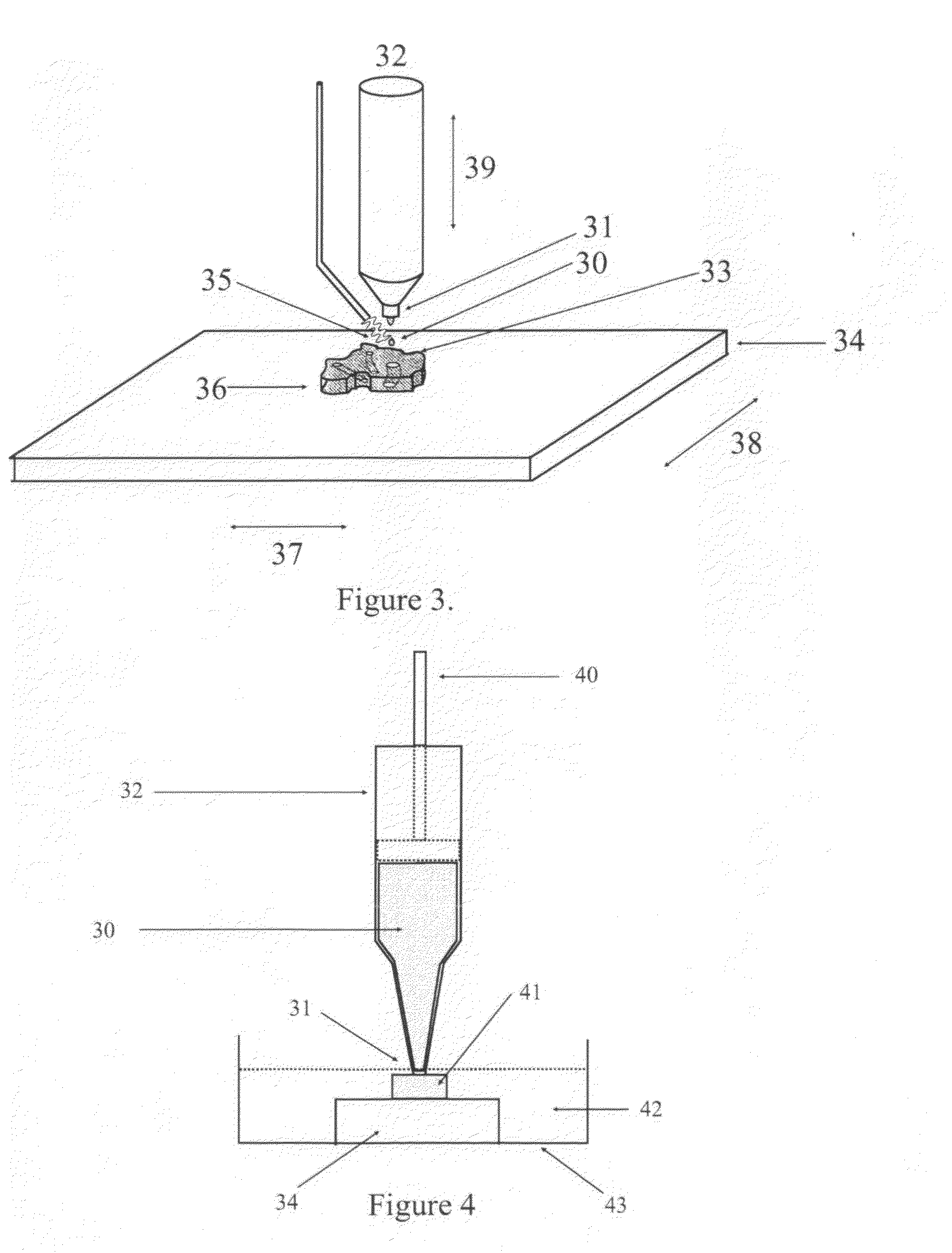
[0073]The HAP powder mixture was ground with the liquid mixture in proportions of 73% powder to 27% liquid in a mortar and pestle on a vibration table until the mixture was fully wetted and flowed under vibration. This mixture was introduced into a syringe with a diameter of 2 mm in which the plunger was connected to a stepping motor which could be controlled by a computer so it could dispense a controlled amount of material by volume over a period of time.

[0074]The substrate was an a...

example 2

[0075]The powders were varied in proportion from Example 1, as follows:

62.5% P263S HAP fully sintered, monomodal particle size distribution <10 μm

37.5% PS221S BM168 fully sintered, ball milled, bimodal <20 μm

and mixed with the liquid mixture from Example 1 in the identical proportions.

[0076]The procedure for direct writing this ceramic was as in Example 1 including the drying and firing of the resulting component. This ceramic had lower overall shrinkage than the material produced in Example 1 and had a fired porosity of 26%.

example 3

[0077]This composition used the same type and proportions of HAP ceramic powders as in Example 1 and mixed in the same way but the liquid mixture comprised:

47% Morrisol AS 2040

[0078]47% Metalflo 4000 colloidal graphite

5.6% Glycerol

0.4% Dispex A40

[0079]As in Example 1. the powder and liquid mixtures were mixed in proportions 73% powder to 27% liquid mixture. This mixture was dispensed through a 1 mm diameter syringe orifice and processed by direct write as in Example 1 including the drying process. The firing cycle consisted of heating to 600° C. at a rate of 3° C. per minute and holding at 600° C. for 1 hour then rising to 1250° C. at 5° C. per minute and holding at this temperature for one hour. The resulting component had inherent micro-porosity of several microns which was thought beneficial for bone growth and was too fine to be written in by the direct write process.


PUM

PropertyMeasurementUnit
Temperatureaaaaaaaaaa
Percent by massaaaaaaaaaa

Abstract

The freeze casting process for preparing a green shaped article such as a biocompatible bioceramic prosthesis or implant, comprises: a) providing a substrate at an initial predetermined spacing from one or more liquid dispensing outlets; b) writing a predetermined amount of a liquid formulation from at least one of the outlets onto the substrate, the formulation comprising: 8 to 99.99% by weight of a liquid sol comprising a liquid carrier and from 5 to 50% by weight, based on the weight of the carrier, of colloidally dispersed nanoparticles having a mean particle size in the range 0.25 to 100 nm; 92 to 0% by weight of a mineral powder having a mean particle size greater than 0.1 micron, and 0.01 to 10% by weight of at least one surfactant, freezing point depressant and / or rheology modifier; c) cooling the liquid formulation on the substrate so as to at least partially freeze the carrier on the cooled substrate; d) increasing the spacing between the one or more dispensing outlets and substrate to a further predetermined spacing; e) writing a further predetermined amount of the liquid formulation from at least one of the outlets either on to the substrate or on to deposit formed in steps b) and c) f) cooling the liquid formulation so as to at least partially freeze the liquid carrier on the substrate and / or on the deposit; and g) optionally repeating steps (d), (e) and (f) one or more times.

Description

BACKGROUND TO THE INVENTION[0001]The present invention relates to a freeze casting process using ceramic materials or the like, enabling production of complex articles such as those required in medical applications such as implants and prosthesis.[0002]Ceramic materials intended for uses such as bone scaffolds and the like are known as bioceramics; they offer particular advantages for the production of implants compared with more conventional metallic materials such as cobalt, chromium or titanium. Bioceramic materials can be tailored to be fully resorted over time and thus be replaced with natural tissue. Bioactive rather than simply biocompatible implants are preferred because they eliminate the risk of long term rejection and other associated complications. Bioceramics can be implanted into bone fractures in place of missing bone. A first category of bioceramics is in the form of highly porous scaffolds having biocompatible body-soluble compositions which allow bone to grow throu...

Claims


Application Information

Patent Timeline
01 Jul 2010
Publication
US20100167020A1
IPC
B32B3/10; B28B5/00; B28B1/00
CPC
A61F2/28; Y10T428/24802; A61F2/30942; A61F2002/2817; A61F2002/30062; A61F2002/3092; A61F2002/30952; A61F2002/30968
Inventors
JONES, RONALD; TODHUNTER, RAYMOND