
Novel nanocomposite for sustainability of infrastructure

a technology of infrastructure and nanocomposites, applied in the field of nanocomposites, can solve the problems of high cost of cnt raw materials and difficulty in its processing and application, large amount of green house gas emission, and susceptibility to deterioration in severe environments, and achieve significant social, economic and environmental benefits, high toughness, and high tensile strength

Inactive Publication Date: 2011-09-15
AUBURN UNIV +1
View PDF33 Cites 21 Cited by
  • Summary
  • Abstract
  • Description
  • Claims
  • Application Information

AI Technical Summary

Benefits of technology

[0009]A nanocomposite has significant social, economic and environmental benefits. By having high tensile strength and high toughness, a large number of opportunities of applying fly ashes are opened up. Besides replacing ordinary Portland cement, the nanocomposite is able to be used as an inorganic adhesive / resin to make fiber reinforced inorganic composites. The composite is fire resistant and has no volatile organic compounds. Due to its multifunctional character, the nanocomposite is able to be used as a sensing element in intelligent structures, corrosion protection coating for concrete and steel structures and even electronic devices. Besides the construction industry, many other industries, such as aerospace and automotive, are also able to benefit by using the nanocomposite.

Problems solved by technology

OPC has two inherent drawbacks: large amount of green house gases emission and susceptibility to deterioration in severe environments.
However, the challenges remain in the high cost of CNT raw materials and the difficulty in its processing and applications.
For example, vacuum or inert gas protection, high temperature and / or high energy density are needed for the production of CNT, e.g., arc-discharge, laser ablation and chemical vapor deposition (CVD) approaches, which make the cost of as-produced CNT high.
In addition, strong van der Waals force induced poor solubility / dispersibility is another factor that restricts the application of CNT, especially in reinforcing composite materials.
As an attempt to address the challenges mentioned above, some reports discussed to embed CNT into carbon fibers through conventional thermal heating process, and CVD methods, which are able to partially solve the dispersibility issue, but the reaction setup is still costly and complicated, and the process is time-consuming and energy inefficient due to the target-less volumetric heating.

Method used


Image

  • Novel nanocomposite for sustainability of infrastructure
  • Novel nanocomposite for sustainability of infrastructure
  • Novel nanocomposite for sustainability of infrastructure

Examples


experiment # 1

Experiment #1

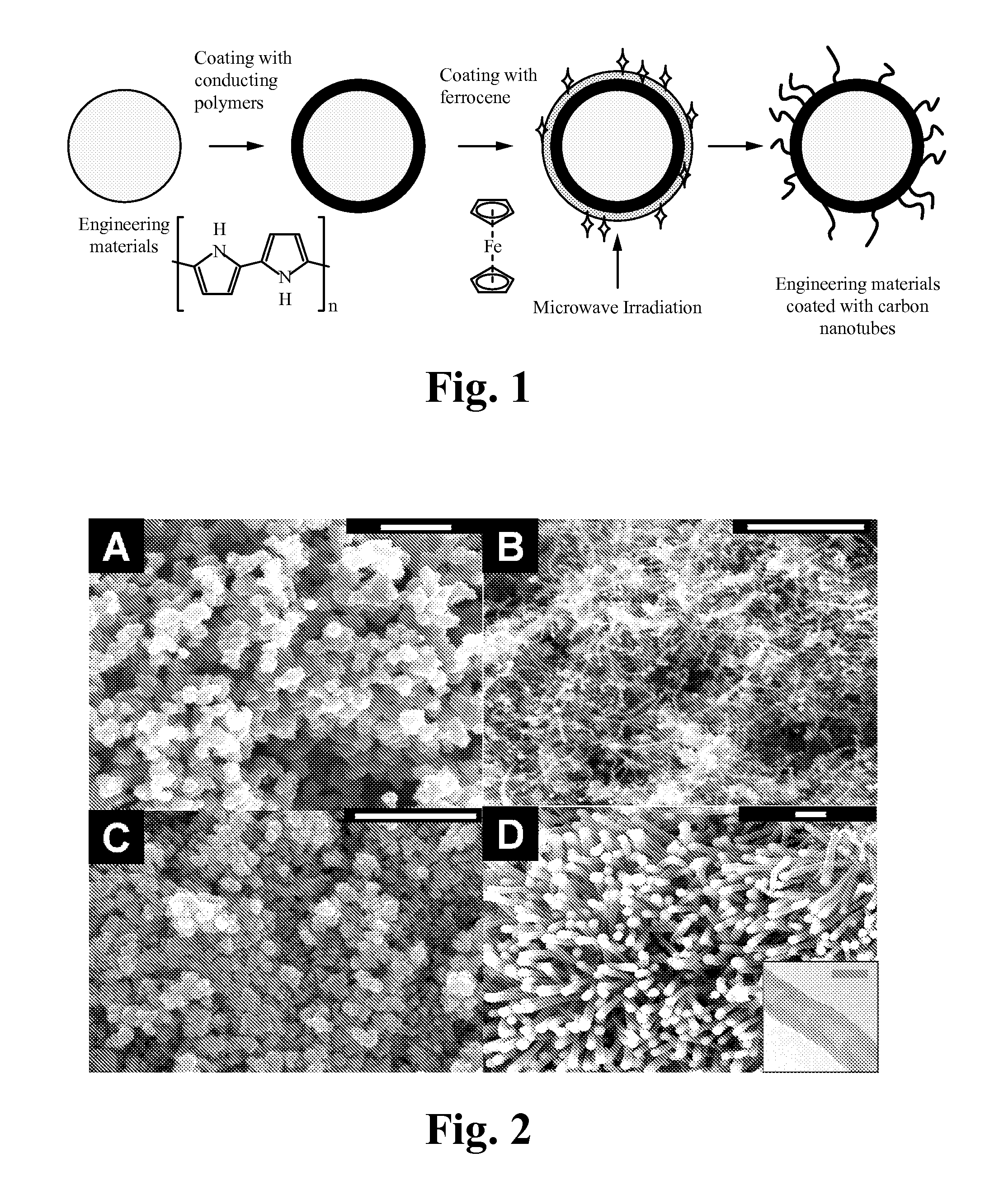
[0047]In situ deposition of conducting polymer on fly ash:

one gram of fly ash was stirred in 60 ml of 0.2M solution of pyrrole in water. To this mixture was added 40 ml of a 0.04M solution of the oxidant ammonium peroxydisulfate, also in water. After 1 hour, the resulting dark precipitate of polypyrrole coated fly ash was suction filtered, washed with copious amounts of water and acetone and dried under a dynamic vacuum at 50° C. for 12 hours.

[0048]Microwave treatment: the polypyrrole coated fly ash is able to then be mixed well with ferrocene (preferably through a fast spinning mixer) at different weight ratio, for example a one to one ratio. Upon 10 seconds of irradiation using a standard (household) microwave, the mixture is heated up and the ferrocene is decomposed to iron catalyst and carbon source, then followed up by quick carbon nanotube growth on the fly ash surface.

experiment # 2

Experiment #2

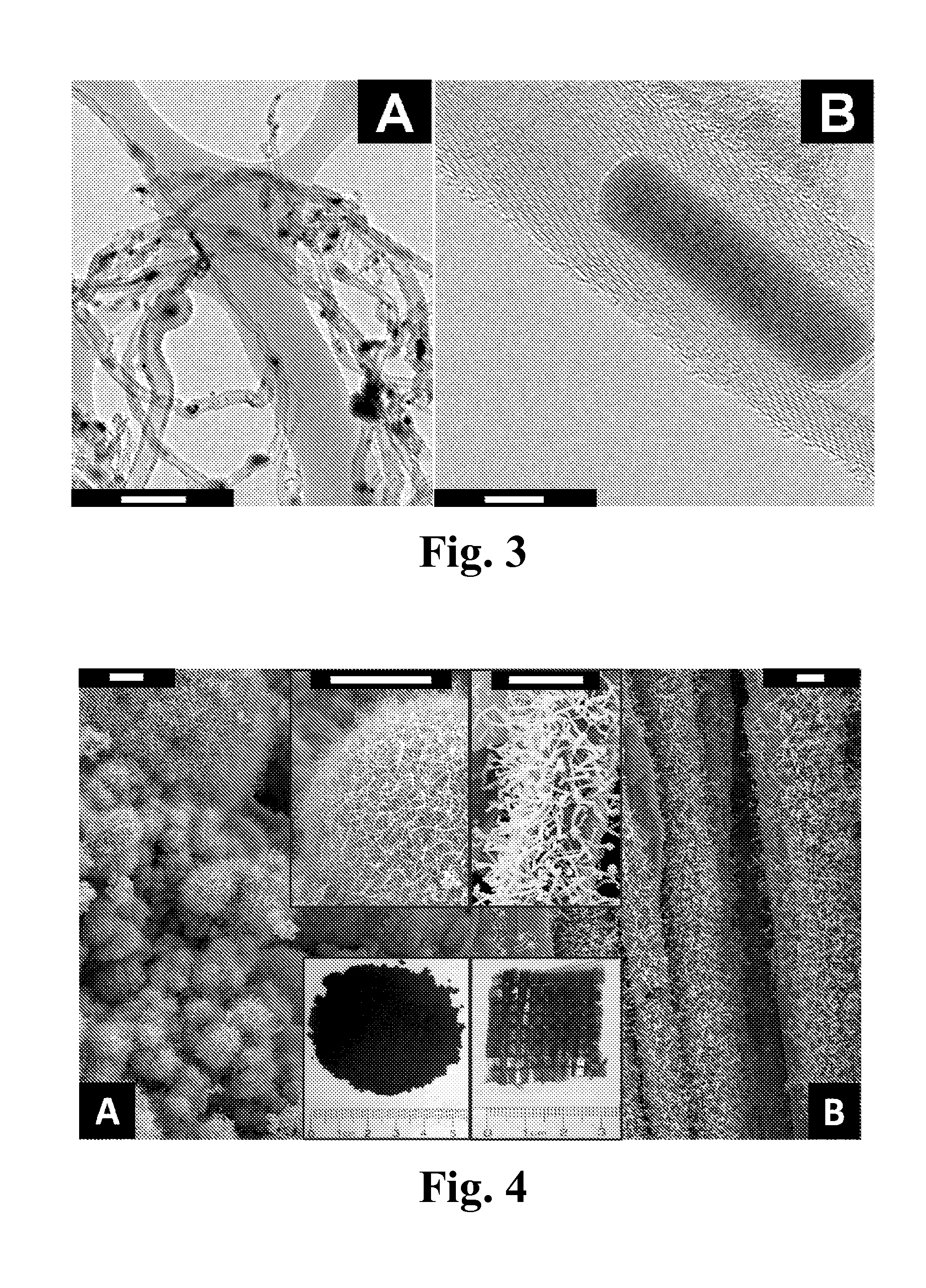
[0049]Conducting PPy.Cl coated fly ash and glass fiber cloth were selected as the substrate materials. 10 g powder of the fly ash-CNT nanocomposites is easily produced using this Poptube approach within 10 minutes in the lab (as shown in insert of image A in FIG. 4), and make CNT coated glass fiber fabrics with dimension at 1 inch×1 inch (as shown in insert of image B in FIG. 4), which depends on the size of the container in the microwave oven.

[0050]These CNT-decorated engineering materials are able to be used as multifunctional fillers into a polymer matrix, or construction materials to build intelligent structures, in order to enhance the electrical and thermal conductivity and mechanical strength. To demonstrate the applicability of this strategy, CNT decorated glass microballoons, as illustrated in Image C of FIG. 8, were used as filler to enhance the mechanical characteristics of epoxy based conventional syntactic foam (SF). The CNT grown amino-silane treated glass...

experiment # 3

Experiment #3

Synthesis of Conductive Polypyrrole Coated Engineering Materials

[0052]In a typical experiment, 1 g fly ash (glass fiber, glass balloon or others) is dispersed in 60 mL 1M HCl under magnetically stirring for 10 minutes, pyrrole (0.24 M) was then added into the above dispersed glass fiber / HCl mixture suspension, then stirred for 10 minutes. After that, 0.03 M ammonium peroxydisulfate (APS) was added into the solution mixture and stirring for 4 hours resulting in polypyrrole coated fly ash in the form of dark precipitates. The resulting black precipitate of polypyrrole coated fly ash was suction filtered, washed with copious amounts of aq. 1 M HCl (3×100 mL) and acetone (3×100 mL) and dried under freeze dry for 12 hours. The yield of polypyrrole coated fly ash was ˜1200 mg.


PUM

PropertyMeasurementUnit
Temperatureaaaaaaaaaa
Timeaaaaaaaaaa
Temperatureaaaaaaaaaa

Abstract

A nanocomposite has significant social, economic and environmental benefits. By having high tensile strength and high toughness, a large number of opportunities of applying fly ashes are opened up. Besides replacing ordinary Portland cement, the nanocomposite is able to be used as an inorganic adhesive / resin to make fiber reinforced inorganic composites. The composite is fire resistant and has no volatile organic compounds. Due to its multifunctional character, the nanocomposite is able to be used as a sensing element in intelligent structures, corrosion protection coating for concrete and steel structures and even electronic devices.

Description

CROSS-REFERENCE TO RELATED APPLICATION(S)[0001]This application claims priority under 35 U.S.C. §119(e) of the U.S. Provisional Patent Application Ser. No. 61 / 309,262, filed Mar. 1, 2010 and titled, “A NOVEL GEOPOLYMERIC NANOCOMPOSITE FOR SUSTAINABILITY OF INFRASTRUCTURE.” The Provisional Patent Application Ser. No. 61 / 309,262, filed Mar. 1, 2010 and titled, “A NOVEL GEOPOLYMERIC NANOCOMPOSITE FOR SUSTAINABILITY OF INFRASTRUCTURE,” is also hereby incorporated by reference in its entirety for all purposes.GOVERNMENT LICENSE RIGHTS[0002]The U.S. Government has a paid-up license in this invention and the right in limited circumstances to require the patent owner to license others on reasonable terms as provided for by the terms of Contract / Grant No. 1000491 and 1000580 awarded by NSF on May 1, 2010.FIELD OF THE INVENTION[0003]The present invention relates to the field of nanocomposites. More specifically, the present invention relates to carbon nanotubes for sustainability of infrastru...

Claims


Application Information

Patent Timeline
IPC IPC(8): B01J19/10B05D7/00B82Y40/00
CPCB82Y30/00D06M11/74C01B31/0233C04B20/1014C04B20/1055C04B28/006B82Y40/00D06M10/003C04B18/08C04B7/02C04B14/026C04B14/106C04B14/22C04B14/42C04B14/386C04B14/4668C04B16/0691C04B18/22C04B18/141C01B32/162Y02W30/91Y02P40/10
Inventor WANG, JIALAIZHANG, XINYU
Owner AUBURN UNIV
Learn More