

Conductive paste and electronic part equipped with electrode wiring formed from same
a technology of electrode wiring and electrode wire, which is applied in the direction of single bars/rods/wires/strips conductors, conductors, metal/alloy conductors, etc., can solve the problems of high material cost, limited use of electrode wiring materials, and susceptibility to migration, so as to reduce the electrical resistance of electrode wiring and low cost
- Summary
- Abstract
- Description
- Claims
- Application Information
AI Technical Summary
Benefits of technology
Problems solved by technology
Method used
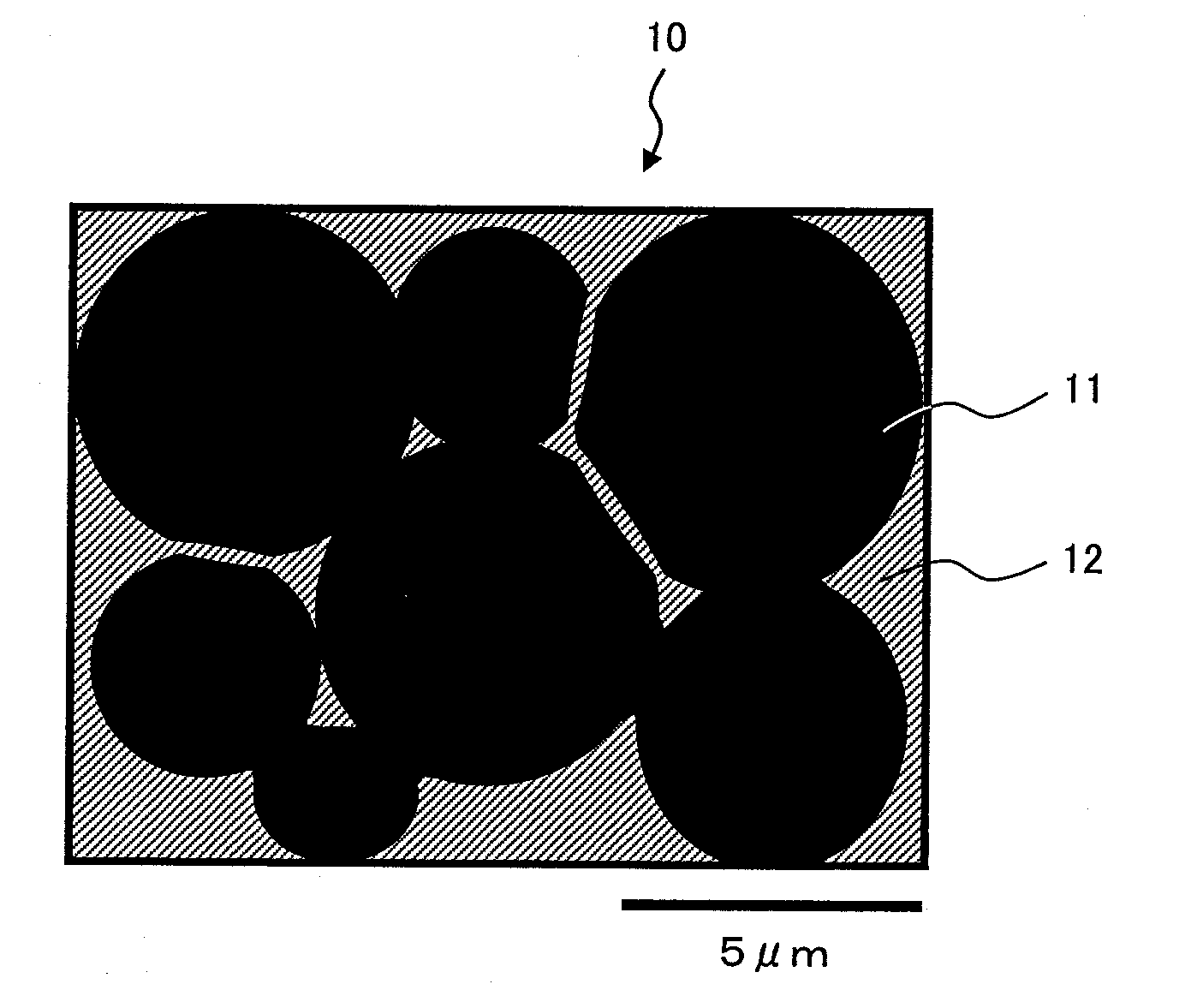
Image

Examples
embodiment 1
[0086](Fabrication of Conductive Glass Particles)
[0087]Conductive glass particles (Glass Sample No. 1-38) having the composition shown in Table 1 below were fabricated. The compositions of Table 1 are shown in mass fraction of each constituent in terms of oxides. Each of these conductive glass samples did not contain lead (Pb), which is a substance prohibited by the RoHS directive, and had a composition based on vanadium (V), phosphorus (P), and barium (Ba). As starting materials, vanadium pentoxide (V2O5), phosphorus pentoxide (P2O5), barium carbonate (BaCO3), lithium carbonate (Li2CO3), sodium carbonate (Na2CO3), potassium carbonate (K2CO3), antimony trioxide (Sb2O3), manganese dioxide (MnO2), diiron trioxide (Fe2O3), bismuth trioxide (Bi2O3), zinc oxide (ZnO), tungsten trioxide (WO3), tellurium dioxide (TeO2), copper oxide (CuO), molybdenum trioxide (MoO3), and boron oxide (B2O3) were used. Also, in the case of using barium phosphate (Ba(PO3)2) as a raw material for barium, the a...
embodiment 2
[0114](Preparation of Conductive Paste)
[0115]As metal particles to be contained in a conductive paste, a pure aluminum powder having an average particle size of about 3 μm was prepared. The metal particles were mixed with a conductive glass powder of Glass Sample No. 9, which exhibited excellent results in Embodiment 1, such that the metal particles represented 99.5% by volume and the conductive glass powder represented 0.5% by volume. Then, a binder resin and a solvent were added to the powder mix and the mixture was kneaded to form a conductive paste. As in Embodiment 1, ethyl cellulose was used as the binder resin, and butyl carbitol acetate was used as the solvent. Conductive pastes formed from glass powders of Comparative Example 1 and Comparative Example 2 were also fabricated.
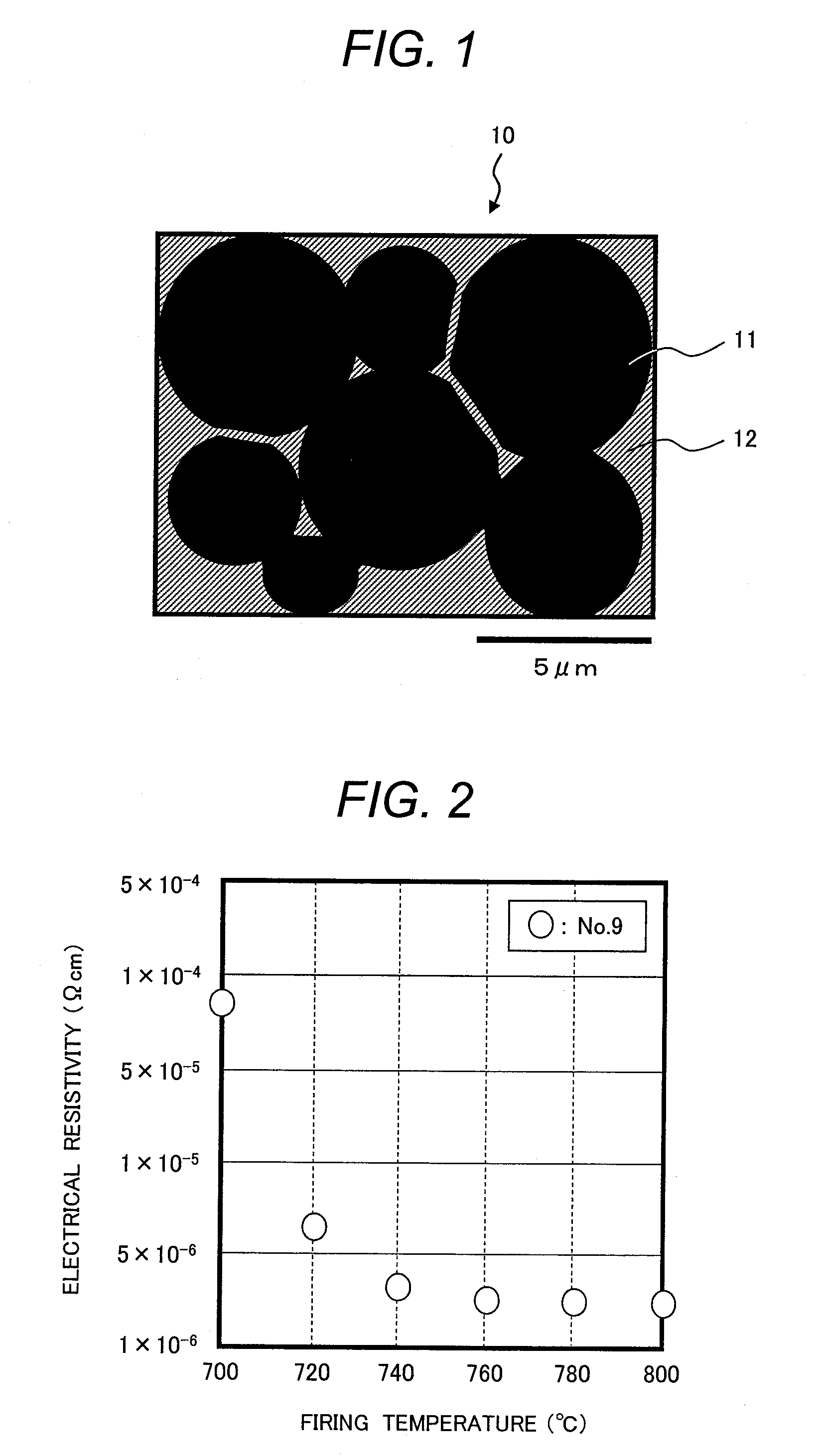
[0116](Fabrication of Electrode Wiring and Measurement of Electrical Resistivity)
[0117]Electrode wiring was formed in the same procedures as those in Embodiment 1. This time, electrode wiring samples wer...
embodiment 3
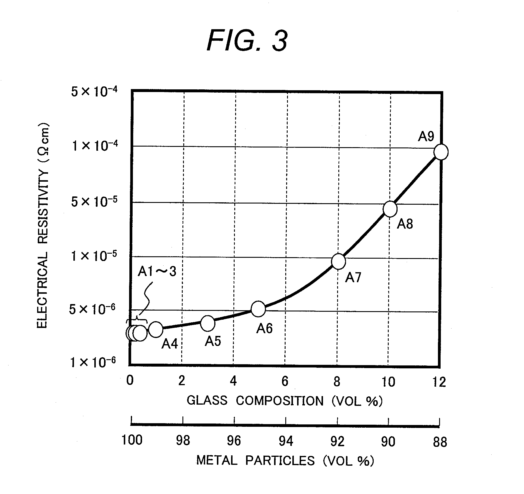
[0122][Examination of Volume Fractions of Metal Particles and Conductive Glass in Electrode Wiring]
[0123]Next, the volume fractions of metal particles and a conductive glass in electrode wiring were examined. The same pure aluminum powder and conductive glass powder of Glass Sample No. 9 as those used in Embodiment 2 were compounded in volume fractions shown in Table 2. Then, the same binder resin and solvent as those in Embodiment 1 were added to the powder mix and the mixture was kneaded to form conductive paste samples (Sample No. A1-A9). Electrode wiring samples were formed from these conductive paste samples under the same conditions as those in Embodiment 1.
[0124]The adhesion strength of each electrode wiring sample was evaluated by a peel test, in which commercially available adhesive cellophane tape was attached to each electrode sample and then peeled off from it. The evaluation criteria were as follows: if almost all of the aluminum particles peeled off, the samples were e...
PUM
| Property | Measurement | Unit |
|---|---|---|
| particle size | aaaaa | aaaaa |
| particle size | aaaaa | aaaaa |
| particle size | aaaaa | aaaaa |
Abstract
Description
Claims
Application Information