
Rechargeable electrochemical energy storage device

a rechargeable, energy storage technology, applied in the direction of non-aqueous electrolyte cells, cell components, batteries, etc., can solve the problems of poor cycling stability of metal batteries, limited charge/discharge cycling stability of non-dissolving electro-active materials, etc., to achieve the effect of reducing or nearly eliminating the weight of air electrodes, improving energy density, and large theoretical capacitance of air electrodes

Inactive Publication Date: 2012-06-07
IMRA AMERICA
View PDF5 Cites 51 Cited by
  • Summary
  • Abstract
  • Description
  • Claims
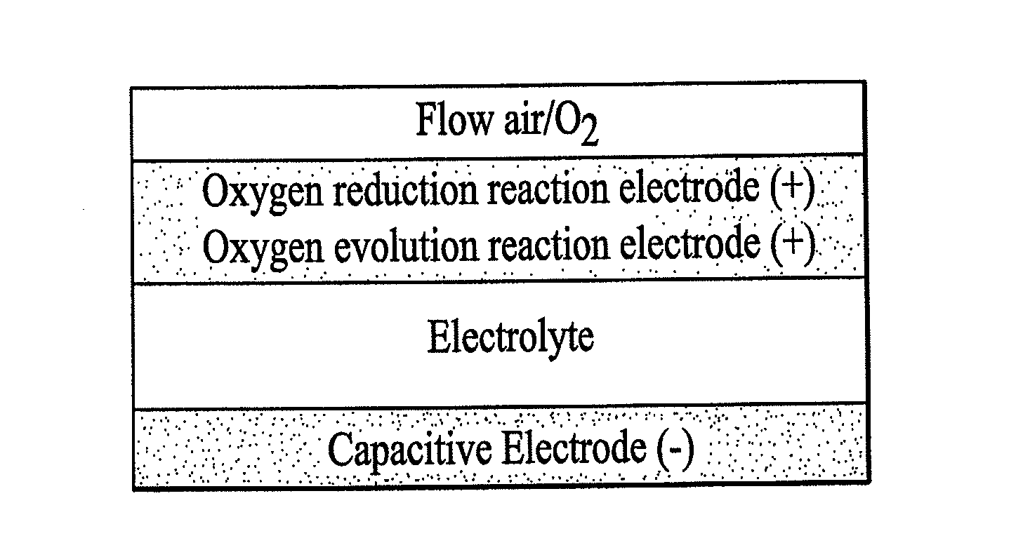
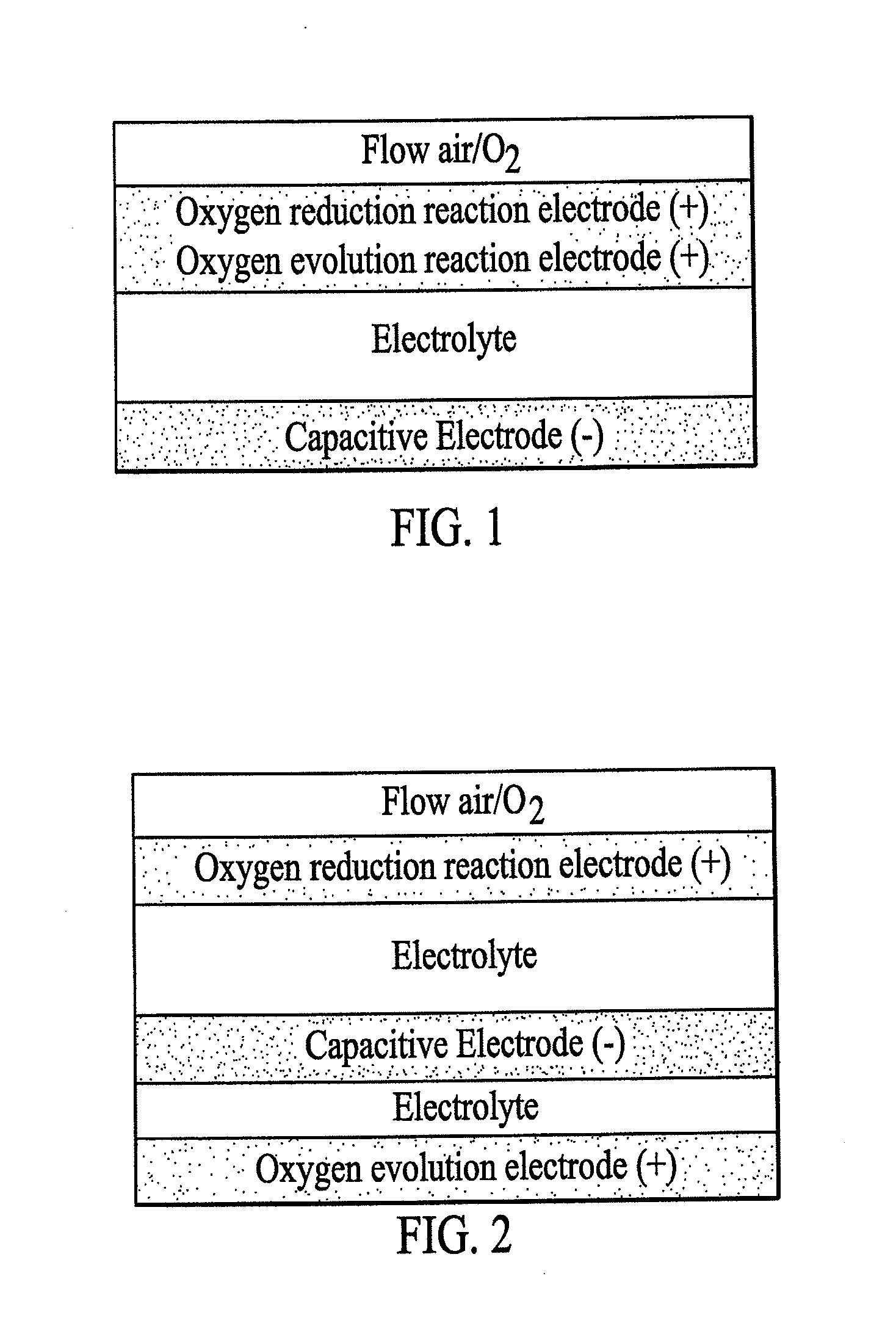
  • Application Information

AI Technical Summary

Benefits of technology

[0008]A general object of this invention, therefore, is to provide electrochemically rechargeable energy storage devices with good stability based on various combinations of air electrodes, electro-inert materials, electro-active materials, and electrolytes.
[0010]In at least one embodiment, a hybrid device comprises a capacitive electrode with the similar function as in an electrochemical capacitor and a second electrode with the same function as an air electrode from rechargeable metal-air batteries. One electrode may include a capacitive material that stores energy through non-faradic reactions and the other electrode may include a material that acts as a catalyst or catalysts for both oxygen reduction and evolution. This energy storage device is expected to have improved energy density over symmetric double layer capacitors by greatly reducing or nearly eliminating the weight of the air electrode. For example, the energy density of an electrochemical capacitor can be calculated as 1 / (mTCT)=1 / (mnCn)+1 / (mpCp) as we discussed above. With an efficient catalyst, the theoretical capacitance for the air electrode is unlimited large. Therefore, the weight for the air electrode can be negligible small compared to the material weight at the negative electrode. The specific capacitance of the device will be the same as the specific capacitance of the negative electrode. For an activated carbon with 280 F / g capacity, the total capacitance of a capacitor with air electrode is 280 F / g, while the value is 70 F / g for the corresponding symmetric activated carbon / activated carbon capacitor.
[0011]In at least one embodiment, a hybrid device comprises a capacitive electrode with the similar function as in an electrochemical capacitor / battery and a second electrode with the same function as an air electrode from rechargeable metal-air batteries. The hybrid energy storage device will have improved cycling stability and / or improved energy density over the prior art metal-air batteries by using wisely choosed negative electrode materials such as electro-inert carbonaceous materials, electro-active silicon / carbon composites, and electro-active compounds. In one example, the cycling stability of zinc-air batteries will be improved if zinc is replaced by a carbonaceous material since the carbonaceous material can reversibly store energy through non-faradic reactions. In another example, the metallic lithium negative electrode may be replaced with a silicon / carbon composite in non-aqueous lithium-air batteries. The cycling stability of the composite negative electrode could be much better than pure lithium as being proved in lithium-ion batteries research. Silicon tends to form alloys with lithium ions during the charge process and release lithium ions during the discharge process. Unlike lithium, silicon maintains its solid morphology during the cycling process. By constraining the volume change (as high as 400%) with carbon, at least a few hundred charge / discharge cycles have been obtained for a silicon / carbon composite electrode in a non-aqueous electrolyte. Compared to prior art electro-active carbonaceous material as the negative material, a silicon / carbon composite could provide much higher energy density (theoretical specific capacity for silicon: 4200 mAh / g) while maintaining a comparable cycling stability. In a third example, a compound such as Li4Ti5O12 could be used as the negative electrode material. The volume expansion / contraction during the lithium insertion / extraction process is negligible for Li4Ti5O12. A hybrid device built on Li4Ti5O12 will have improved cycling stability over the prior art metal-air batteries.
[0012]In at least one embodiment, the air electrode could be used as the negative electrode instead of using as a positive electrode as in the prior art air batteries. The application of air electrode as the negative electrode may provide us a safe rechargeable energy storage device with good energy density. Current safe lithium-ion batteries focus on using Li4Ti5O12 as the negative electrode material because of its relatively high redox potential (˜1.5 V vs. Li / Li) and negligible volume expansion / contraction during cycling. The theoretical energy density of this negative material, however, is only 175 mAh / g, which limits the overall energy density of an energy storage device. The device's energy density could be doubled with an air electrode operated at similar redox potentials by assuming the positive electrode has a capacity of 175 mAh / g.
[0013]In at least one embodiment, the electrolyte could be neutral solution. The prior art aqueous metal-air batteries are limited in using highly alkaline electrolytes. The high corrosive properties of highly alkaline solutions may limit the cycling stability of an air catalyst. A mild neutral electrolyte may extend the stability of the air catalyst. Moreover, the operating voltage window of the device may be extended since the potentials of oxygen reduction / evolution are expected to be positively shifted because of a decrease in pH while the operating potential of the negative electrode could be maintained at similar range because of the overpotential formed at the negative electrode.

Problems solved by technology

Batteries based on metals, however, generally have poor cycling stabilities during the charge / discharge process.
Similar problems have been encountered in lithium batteries, where the metallic lithium dissolves as lithium ions during discharging and the lithium ions deposit as metallic lithium during charging.
These non-dissolving electro-active materials, however, may still have limited charge / discharge cycling stability mainly because of the volume change associated with the faradic reactions.
The lithium ion insertion and extraction processes will cause the volume of the non-dissolving electro-active material to expand and to contract, which will disrupt the original compact structure of the electrode film resulting in the loss of electric connections among the electro-active particles, which in turn results in the fading of capacity during the charge / discharge cycling.
Unlike the dissolution / deposition process, instability from the volume expansion / contraction process can be limited by controlling the material architecture in the electrode.
Electrochemical capacitors, however, are limited in energy densities.
The maximum energy density that can be stored therefore is limited by the surface area of the electrode material.
Regardless of the advantage of electro-active materials, charge capacities of these materials, however, are still limited (for example theoretical capacity for NiOOH is 292 mAh / g).
This system, however, is generally limited by its poor charge / discharge cycling stability, which is mainly caused by the instability of the negative electrode during cycling.
The prior art air batteries have been limited into either using metals as negative electrode materials in aqueous alkaline electrolyte or metallic lithium as the negative electrode material in organic electrolyte except in very few cases where silicon and metal hydrides were used as the negative electrode materials in aqueous alkaline electrolyte and carbonaceous materials and metals were used as the negative intercalation materials in organic electrolyte.
For zinc-air, sodium-air, magnesium-air, and lithium-air batteries, the instability is mainly because of the metal dissolution / deposition process during the charge / discharge cycling process.
The stability is still limited to tens of cycles because of the stability limitation in zinc electrode.
This coating, however, is not expected to solve the stability issues because of the dramatic volume change of the lithium film during the lithium dissolution / deposition process.
The formed silicate ions are almost impossible to be reduced back into silicon.
The cycling stability of metal hydrides, however, is limited to at most 1500 cycles as in nickel metal hydride alkaline batteries.
Li / Li+), which may limit the long-term stability and cause safety issues.
An electro-active carbonaceous material will experience volume expansion / contraction as other negative electrode materials, which limits its cycling stability from tens to a few thousands of cycles.
Moreover, electro-active carbonaceous materials may be limited in energy capacities.
These metals will experience dramatic volume expansion / contraction during charge / discharge cycling.
A battery with a pure metal negative electrode will have limited cycling stability because of the volume expansion / contraction.
In this sense, prior art negative materials for non-aqueous air batteries are limited either in specific capacity (carbons, 374 mAh / g or 834 mAh / cm3 for graphite) or in cycling stability (lithium and metals).
Besides being limited in the negative electrode materials, the prior art metal-air batteries have several other limitations.
The prior art metal-air batteries are limited in using air electrode as the positive electrode, while the possibility of using air electrode as the negative electrode has not been disclosed.
The prior art aqueous metal-air batteries are limited in using a highly corrosive alkaline solution as the electrolyte, while the possibility of using a mild neutral solution or an acidic solution has not been disclosed.

Method used


Image

  • Rechargeable electrochemical energy storage device
  • Rechargeable electrochemical energy storage device
  • Rechargeable electrochemical energy storage device

Examples


examples

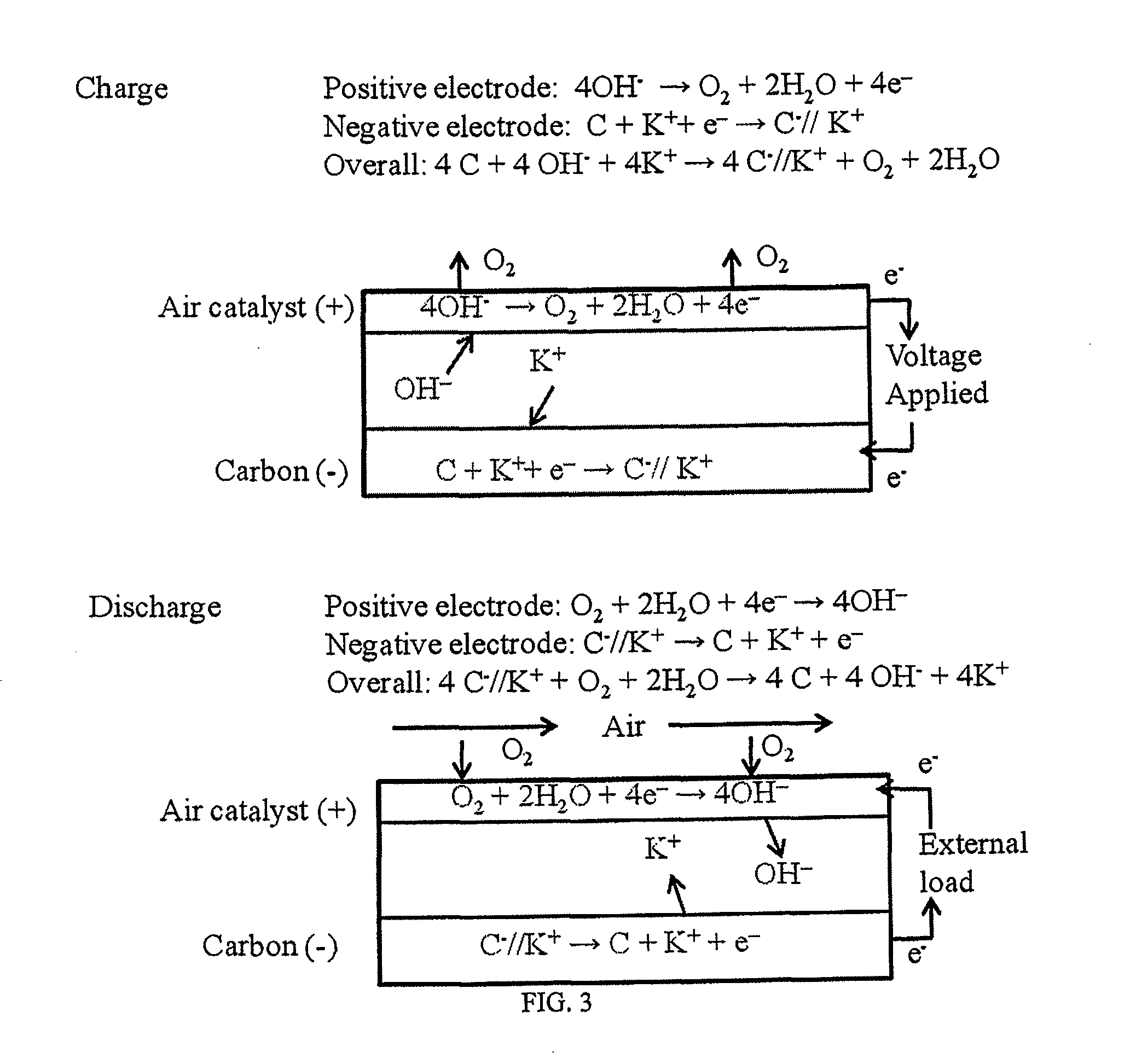
[0050]A two-electrode test cell of the asymmetric energy storage device was fabricated by using an air electrode from a commercial zinc-air battery as the positive electrode and an activated carbon capacitive electrode as the negative electrode. A mercury-mercuric oxide (Hg / HgO) reference electrode was added into the cell to monitor the potential evolution of the air electrode during charge and discharge cycles. The air electrode was obtained by dissembling a commercial zinc-air button cell and then rinsing the electrode with de-ionized water. 1 M KOH was used as the electrolyte for the test cell. Electrochemical testing was carried out in a battery testing instrument (ARBIN). A graph of constant current charge / discharge curves is shown in FIG. 8. The charge / discharge curves are almost linear, which is typical for double-layer capacitance (non-faradic reactions). The cell is stable for the tested cycles. No visually observable decrease in charging / discharge time is observed. The air...


PUM

PropertyMeasurementUnit
mass ratioaaaaaaaaaa
charge capacitiesaaaaaaaaaa
voltage potentialsaaaaaaaaaa

Abstract

A rechargeable energy storage device is disclosed. In at least one embodiment the energy storage device includes an air electrode providing an electrochemical process comprising reduction and evolution of oxygen and a capacitive electrode enables an electrode process consisting of non-faradic reactions based on ion absorption / desorption and / or faradic reactions. This rechargeable energy storage device is a hybrid system of fuel cells and ultracapacitors, pseudocapacitors, and / or secondary batteries.

Description

FIELD OF INVENTION[0001]This invention relates to energy storage devices. More specifically, the present invention relates to a type of rechargeable energy storage devices that have both air electrodes and capacitive electrodes for energy storage.BACKGROUND OF INVENTION[0002]Batteries and capacitors represent two most important systems for energy storage, with applications in electronics, electric vehicles, telephone communication systems, power supplies, and many other applications.[0003]A battery is used to store electricity by converting electric energy into chemical energy during charging and converting chemical energy back into electric energy during discharging. The energy is stored through chemical reactions, which are often associated with the change of oxidation states of active metal species (faradic reactions). Electro-active materials are often the active component in batteries since they can provide redox reactions for energy storage. Because of the high theoretical ene...

Claims


Application Information

Patent Timeline
Patent Type & Authority Applications(United States)
IPC IPC(8): H01G9/008H01M10/05H01M8/10H01M12/00
CPCH01G11/02H01G11/06H01G11/46H01G11/54H01M4/90Y02E60/13H01M16/00H01M16/003H01M16/006Y02T10/7022Y02E60/50H01M12/08Y02E60/10Y02T10/70H01G9/008H01M4/13H01M8/10H01M10/05H01M12/06H01M4/8605H01M4/9016H01M4/9041H01M12/02H01M14/00H01M2220/20H01M2220/30
Inventor TAN, BINGHU, ZHENDONGCHE, YONG
Owner IMRA AMERICA
Learn More