Ionic electro-conductive resin and electro-conductive member for electrophotography
- Summary
- Abstract
- Description
- Claims
- Application Information
AI Technical Summary
Benefits of technology
Problems solved by technology
Method used
Image

Examples
first embodiment
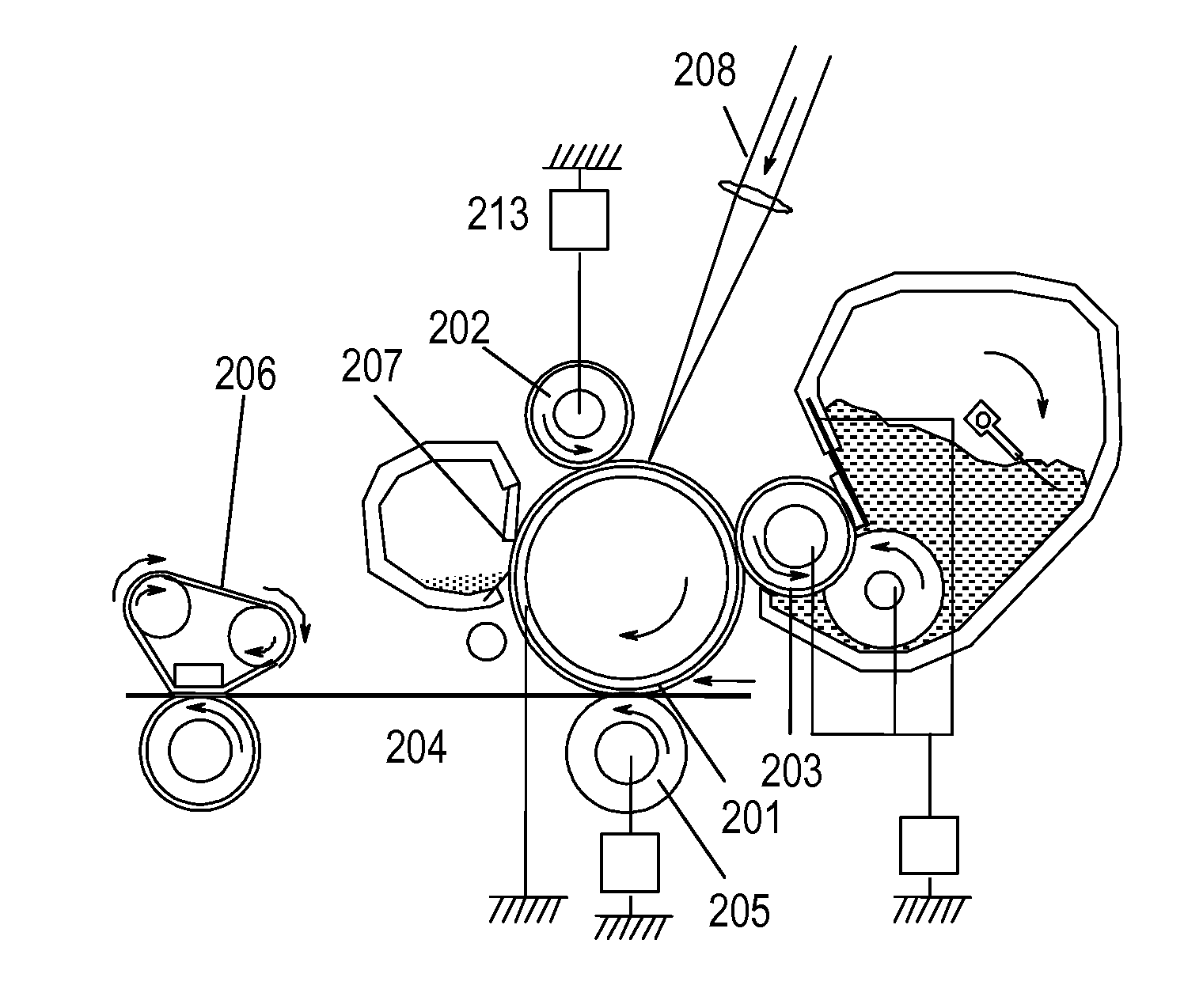
[0026]An electro-conductive member for electrophotography related to the present invention can be used as each of a charging member, a developing member, a transferring member, an antistatic member, and a conveying member such as a sheet-feeding roller in an electrophotographic image forming apparatus. Now, the present invention is described by way of a charging roller as a representative example of the electro-conductive member for electrophotography.
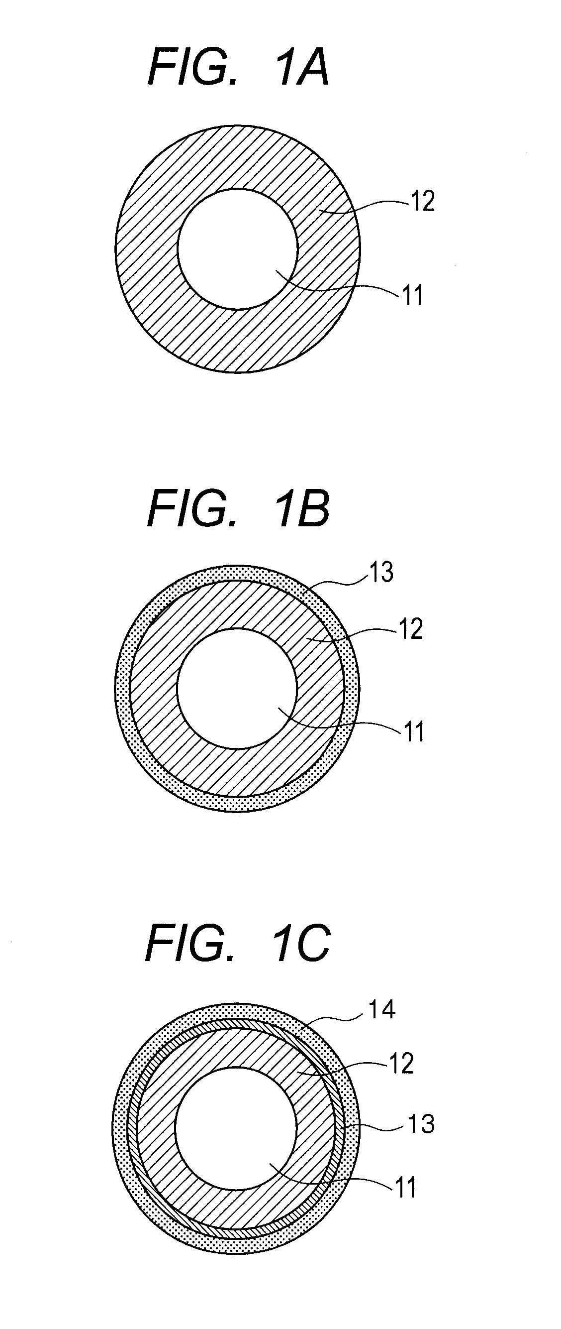
[0027]FIGS. 1A to 1C are each a schematic construction view of a roller-shaped charging member (hereinafter, sometimes referred to as “charging roller”) according to the present invention. As illustrated in FIG. 1A, a first electro-conductive layer 12 is provided on the outer periphery of an electro-conductive mandrel 11. In this case, the first electro-conductive layer 12 contains an ionic electro-conductive resin of the present invention. As illustrated in FIG. 1B, a second electro-conductive layer 13 may be provided on the outer per...
second embodiment
[0082]A second embodiment of the present invention is an electrolyte membrane for a fuel cell.
[0083]A membrane-electrode assembly can be produced by placing electrodes on the ionic electro-conductive resin according to the present invention. The membrane-electrode assembly is constructed of the ionic electro-conductive resin according to the present invention, and catalyst electrodes (an anode and a cathode) opposed to each other across the resin. The catalyst electrodes are each obtained by forming a catalyst layer on a gas diffusion layer. A method of producing the assembly is not particularly limited and a known technology can be employed. The assembly can be produced by a method such as a method involving directly forming, on the ionic electro-conductive resin, a gas diffusion electrode using a catalyst obtained by dispersing and carrying platinum, a platinum-ruthenium alloy, or fine particles thereof on a carrier such as carbon, a method involving hot-pressing the gas diffusion...
example 1
[0112]Production and Evaluations of Charging Roller No. 1;
[0113]The coating liquid No. 1 was applied onto the outer peripheral surface of the rubber roller No. 1 once by dipping, and was then air-dried at normal temperature for 30 minutes or more. Next, the resultant was dried by a circulating hot air dryer set at 80° C. for 1 hour, and was then further dried by a circulating hot air dryer set at 160° C. for 3 hours.
[0114]A dipping application immersion time was regulated to 9 seconds, and a dipping application lifting speed was regulated so that the initial speed was 20 mm / s and the final speed was 2 mm / s. The speed was linearly changed with time from 20 mm / s to 2 mm / s. Thus, a charging roller No. 1 having an ionic electro-conductive resin-containing layer on the outer periphery of an epichlorohydrin rubber electro-conductive layer was produced.
[0115] Evaluation of Environment Dependence of Electrical Resistivity of Charging Roller;
[0116]FIGS. 4A and 4B each illustrate a schematic ...
PUM
| Property | Measurement | Unit |
|---|---|---|
| Electrical conductor | aaaaa | aaaaa |
Abstract
Description
Claims
Application Information
 - Generate Ideas
- Intellectual Property
- Life Sciences
- Materials
- Tech Scout
- Unparalleled Data Quality
- Higher Quality Content
- 60% Fewer Hallucinations
Browse by: Latest US Patents, China's latest patents, Technical Efficacy Thesaurus, Application Domain, Technology Topic, Popular Technical Reports.
© 2025 PatSnap. All rights reserved.Legal|Privacy policy|Modern Slavery Act Transparency Statement|Sitemap|About US| Contact US: help@patsnap.com