Method and system for producing synthesis gas

a technology of synthesis gas and gas, applied in the direction of combustible gas production, combustible gas purification/modification, energy input, etc., can solve the problems of low heating value of synthesis gas at the outlet, low heat exchange efficiency, and large amount of synthesis gas, and achieve low cost and high efficiency.

Inactive Publication Date: 2013-01-24
WUHAN KAIDI ENG TECH RES INST CO LTD
View PDF8 Cites 17 Cited by
  • Summary
  • Abstract
  • Description
  • Claims
  • Application Information

AI Technical Summary

Benefits of technology

[0012]In view of the above-described problems, it is one objective of the invention to provide a method and a system for producing synthetic gas from biomass by pyrolysis that have high efficiency and low cost.

Problems solved by technology

However, the temperature is nonuniform and it has less efficiency of heat exchange, low heating value of the synthesis gas at the outlet, and the synthesis gas contains a large amount of tar.
However, it is sensitive to the characteristics of raw materials.
If the adhesion, thermal stability, moisture content, or ash melting point of raw materials changes, the operation will become abnormal.
Furthermore, in order to ensure normal fluidization of the gasification furnace, it needs to keep lower temperature, and the synthetic gas has a large amount of tar.
Since a large amount of tar is produced in the fixed bed and the fluidized bed, a tar cracking unit and purification equipment must be installed, which results in a complicated process.
Based on current grinding technology, there is no way to grind biomass having much cellulose to a size suitable for the entrained flow bed.
So the entrained flow bed cannot be used for gasification of biomass.
Nowadays, tar cracking and pretreatment of biomass prior to gasification are tough problems for the development of biomass gasification.
In the method, pyrolysis gas and charcoal experience incomplete combustion in the gasifier at around 1000° C., and tar is cracked under high temperature.
Thirdly, the ash and unreacted carbon residue from the reduction reaction is directly discharged, resulting in a low carbon conversion rate.
Finally, the gasifier used in the method is in the form of a fixed bed, since the reduction reaction absorbs heat, the temperature difference between the top and the bottom (the top is about 1000° C. and the bottom is about 500° C.) of the bed is huge, which is an inherent disadvantage of fixed bed.
However, during carbonization stage, solid products are not ground prior to transporting to the reaction coils of the gasifier, which will affect the speed and degree of gasification reaction.
Secondly, since the gasification reaction happens in the reaction coil, a large amount of transport gas is needed, but the transport gas will take away a lot of heat during transporting, and thereby the gasification efficiency is low, the temperature is nonuniform, and the subsequent waste heat recovery system is massive.
Thirdly, it is not economic that newly-produced synthetic gas is used to provide heat for gasification and carbonization.
Fourthly, combustion products (mainly CO2 and H2O) are directly discharged and not fully utilized, resulting in low gasification efficiency.
Finally, the ash and unreacted carbon residue in the synthetic gas are also discharged directly, resulting in low carbon conversion rate.
However, the method has following problems: firstly, heat of the carbonization furnace is supplied by direct combustion of external combustible gas and oxygen; the introduced high-quality external fuel gas greatly increases the energy consumption of the system; secondly, the adopted pyrolysis gas powder feeding system is complicated; when the high temperature pyrolysis gas is mixed with the low temperature carbon powder and fed into the gasification furnace, the mixture can easily be condensed to form tar, causing blockage and influencing the normal operation; finally, the high pressure charcoal produced in the carbonization furnace is fed into the normal pressure milling machine after being decompressed and cooled, so as to be made into powder, and then the carbon powder is pressurized and fed into the gasification furnace by the pyrolysis gas.
The whole process is complicated and high in energy consumption so that the feasibility of the project is bad.
From the above mentioned methods, conventional gasification, whether from biomass or from solid carbon-containing materials, cannot produce synthetic gas with high efficiency and low cost.
Although the technology of independent pyrolysis and gasification can adapt to a variety of biomass and reduce the content of tar in synthetic gas, shortcomings such as nonuniform temperature, large investment in equipment for waste heat recovery, high material consumption, low gasification efficiency, and low carbon conversion rate limit the application of biomass gasification in industry.
Particularly, there is no effective method for gasifying biomass applied to an entrained flow bed.

Method used


Image

  • Method and system for producing synthesis gas
  • Method and system for producing synthesis gas

Examples


example 1

[0065]Take wood as a raw material of biomass. The elemental composition and characteristic data of the dried wood are listed in Table 1.

TABLE 1Elemental composition and characteristic data of the dried woodItemsSymbolUnitValueCarbonCar% (Kg / Kg)39.43HydrogenHar% (Kg / Kg)5.21OxygenOar% (Kg / Kg)38.36NitrogenNar% (Kg / Kg)0.15SulfurSar% (Kg / Kg)0.21ChlorineClar% (Kg / Kg)0.00AshAar% (Kg / Kg)5.00MoistureMar% (Kg / Kg)11.64Ash fusion pointFT° C.1436Low heat valueLHVMJ / Kg14.75

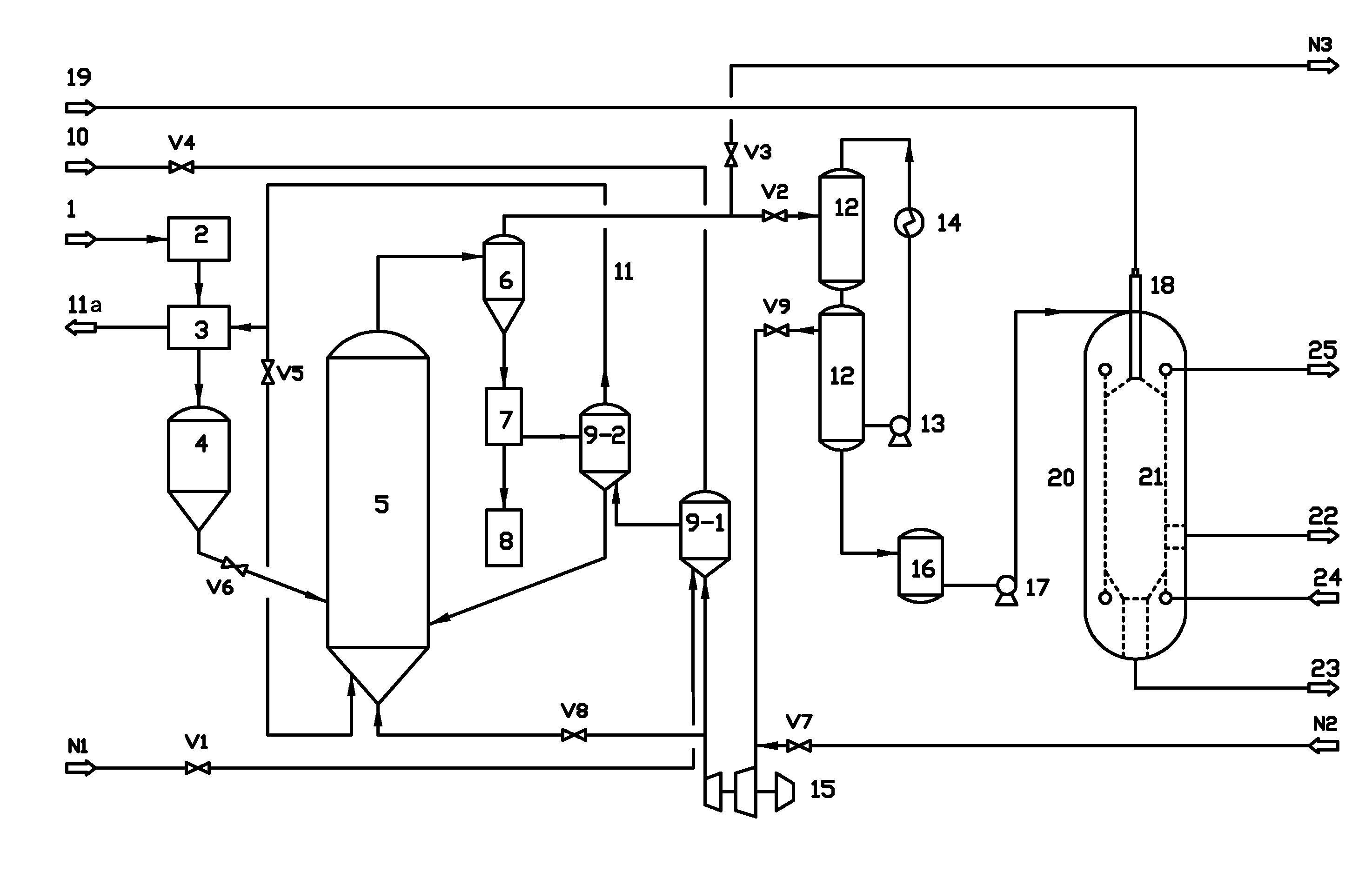
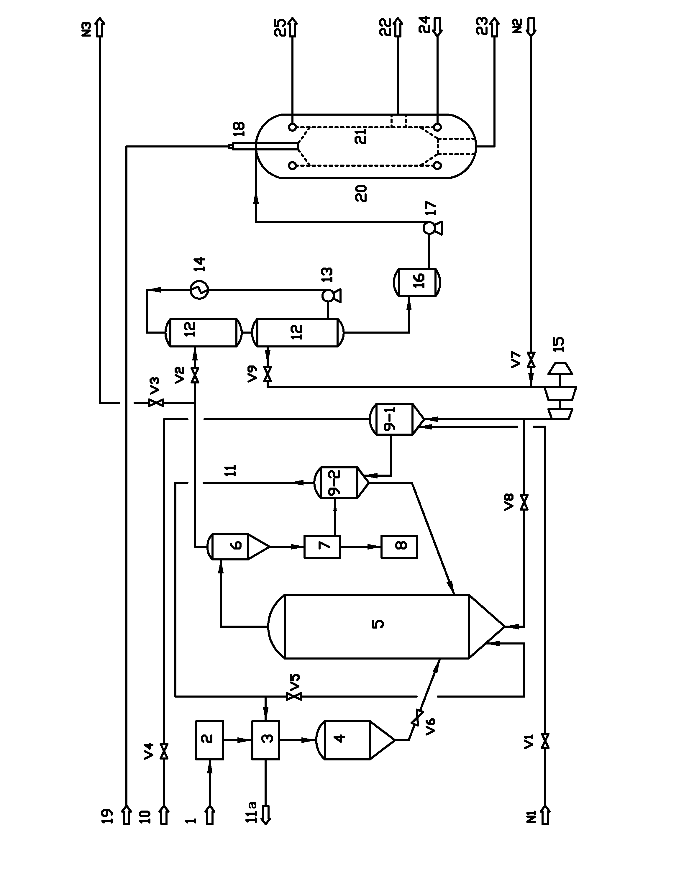
[0066]The main operating conditions are set as follows:[0067]1) the grain diameter of the material at the outlet of the crushing system 2 is 6 mm;[0068]2) the water content of the material at the outlet of the drying system 3 is 15 wt. %;[0069]3) the pressure of the pyrolysis bed 5 is normal pressure and the temperature is controlled at 400° C.;[0070]4) gas phase residence time of the pyrolysis bed 5 is 5 s; and[0071]5) the pressure of the gasification furnace 20 is controlled to be 4.0 MPa (A) and the temperature is controlled...

example 2

[0076]Take wood in Example 1 as a raw material of biomass (Table 1).

[0077]The main operating conditions are set as follows:[0078]1) the grain diameter of the material at the outlet of the crushing system 2 is 5 mm;[0079]2) the water content of the material at the outlet of the drying system 3 is 20 wt. %;[0080]3) the pressure of the pyrolysis bed 5 is normal pressure and the temperature is controlled at 500° C.;[0081]4) gas phase residence time of the pyrolysis bed 5 is 3 s; and[0082]5) the pressure of the gasification furnace 20 is controlled to be 4.0 MPa (A) and the temperature is controlled at 1400° C.

[0083]According to the set conditions above, the main data and performance parameter of the system in the implementation process of the invention are explained in detail with the attached drawing:[0084]1) biological fuel quality yield of the biomass raw material fed to the pyrolysis bed 5 is 60%;[0085]2) dry basis content of CO and H2 in the synthesis gas output by the pipeline 22 ...

example 3

[0087]Take wood in Example 1 as a raw material of biomass (Table 1).

[0088]The main operating conditions are set as follows:[0089]1) the grain diameter of the material at the outlet of the crushing system 2 is 4 mm;[0090]2) the water content of the material at the outlet of the drying system 3 is 10 wt. %;[0091]3) the pressure of the pyrolysis bed 5 is normal pressure and the temperature is controlled at 600° C.;[0092]4) gas phase residence time of the pyrolysis bed 5 is 2 s; and[0093]5) the pressure of the gasification furnace 20 is controlled to be 4.0 MPa (A) and the temperature is controlled at 1400° C.

[0094]According to the set conditions above, the main data and performance parameter of the system in the implementation process of the invention are explained in detail with the attached drawing:[0095]1) biological fuel quality yield of the biomass raw material fed to the pyrolysis bed 5 is 65%;[0096]2) dry basis content of CO and H2 in the synthesis gas output by the pipeline 22 ...


PUM

PropertyMeasurementUnit
temperatureaaaaaaaaaa
particle sizesaaaaaaaaaa
temperatureaaaaaaaaaa

Abstract

A method for producing synthesis gas, including: 1) pre-processing a biomass raw material; 2) pyrolyzing the biomass raw material to yield a pyrolysis gas and a carbon powder; 3) separating the pyrolysis gas from the carbon powder and a solid heat carrier; 4) separating the carbon powder away from the solid heat carrier via a solid-solid separator; 5) conveying the generated pyrolysis gas to a condensate tank for spray condensation, condensing a condensable part in the pyrolysis gas to generate biological fuel oil, pressurizing the generated biological fuel oil by a high pressure oil pump and feeding to a gasification furnace to be gasified; and 6) feeding one part of non-condensable pyrolysis gas to a combustion bed to combust with air, and conveying the other part of the non-condensable pyrolysis gas to the pyrolysis bed as a fluidizing medium.

Description

CROSS-REFERENCE TO RELATED APPLICATIONS[0001]This application is a continuation-in-part of International Patent Application No. PCT / CN2011 / 072061 with an international filing date of Mar. 23, 2011, designating the United States, now pending, and further claims priority benefits to Chinese Patent Application No. 201010132481.3 filed Mar. 23, 2010. The contents of all of the aforementioned applications, including any intervening amendments thereto, are incorporated herein by reference. Inquiries from the public to applicants or assignees concerning this document or the related applications should be directed to: Matthias Scholl P.C., Attn.: Dr. Matthias Scholl Esq., 14781 Memorial Drive, Suite 1319, Houston, Tex. 77079.BACKGROUND OF THE INVENTION[0002]1. Field of the Invention[0003]The invention relates to the production of synthetic gas, and more particularly to a method and a system for producing synthetic gas from biomass by pyrolysis. The method belongs to the technical field of p...

Claims


Application Information

Patent Timeline
Patent Type & Authority Applications(United States)
IPC IPC(8): C10J3/00C10J3/20
CPCC10B49/22C10B53/02C10G2300/1011C10C5/00C10K1/04C10K1/06Y02E50/14C10K1/026Y02P20/145Y02P20/129Y02P30/20Y02E50/10C10J3/66C10B57/10C01B3/22C01B2203/0272
Inventor SONG, KANJIANG, MANYISUN, QINZHANG, SHIRONGZHANG, HAIQINGZHANG, JINQIAO
Owner WUHAN KAIDI ENG TECH RES INST CO LTD
Why Eureka
Try Eureka