Optical fiber with grating and particulate coating

Inactive Publication Date: 2015-05-21
SPARTAN BIOSCIENCE INC
View PDF5 Cites 39 Cited by
  • Summary
  • Abstract
  • Description
  • Claims
  • Application Information

AI Technical Summary

Benefits of technology

[0018]In some embodiments, the size, spacing and permittivity of the metal particles in the particulate coating allow the excitation of surface plasmon resonances (SPR) at the wavelengths of interest. SPR greatly amplifies the fluorescence of fluorescent molecules in a liquid around the fiber because of the large enhancement of electromagnetic field intensity. This SPR effect may be advantageous for applications involving fluorescent molecules, such as real-time PCR with

Problems solved by technology

While this disclosure describes sensing, it does not address, let alone describe or enable heating, and also does not address let alone describe or enable extracting light from the fiber to excite photo-luminescence in materials outside the fiber.
The apparatus described in this reference may be able to achieve heating and temperature sensing, however it does not and cannot achieve fluorescent detection because light cannot pass through the silver film.
In addition, the apparatus requires two separate types of grating, which is more costly to manufacture than a single type of grating.
The trade-off is that high power light is required to heat the silver coating.
This approach requires a light source which consumes more energy and is more expensive

Method used


Image

  • Optical fiber with grating and particulate coating
  • Optical fiber with grating and particulate coating
  • Optical fiber with grating and particulate coating

Examples


example 1

Grating Fabrication

[0066]For the examples described herein, the TFBG was produced using a standard telecommunications single-mode fiber (CORNING SMF 28). One-meter-long fiber strands were placed in a pressurized container that was filled with pure Hydrogen gas at a typical pressure of 2500 psi for a period of at least 14 days. The fiber strands were then taken out of the container and prepared for UV irradiation: a 5-cm-long section of the fiber polymer jacket was removed with a stripping tool to expose the glass cladding. The fiber was connected to a broadband light source (covering the 1510 nm to 1620 nm wavelength range) and to an optical spectrum analyzer. The exposed part of the fiber was positioned on the downstream side of a diffractive grating and exposed to intense pulses of ultraviolet light at 193 nm generated by an excimer laser (any wavelength between 190 nm and 248 nm may be used). The power density of the pulses were 40 mJ / cm2 at the fiber, and the pulse repetition ra...

example 2

Coating Fabrication

[0067]This example describes one kind of particulate coating that will serve as an exemplary embodiment. Silver nanowires were chemically synthesized as described in Sanders et al. (Sanders A W et al. (2006) Nano Lett, 6(8): 1822-1826; the entirety of which is hereby incorporated by reference). The procedure results in highly crystalline nanowires with smooth surfaces.

[0068]In brief, all reagents were obtained from Sigma-Aldrich. All glassware was cleaned using aqua regia, rinsed in 18.2 MΩXcm deionized water, and placed in an oven to dry prior to experimentation. A 50-mL round bottom flask containing 24.0 mL of anhydrous 99.8% ethylene glycol (EG) and a clean stir bar were placed in an oil bath set to 150° C. and allowed to sit for 1 hour. Using a micropipette, 400 μL of 3 mM sodium sulfide dissolved in EG was added to the flask. Ten minutes later, 6 mL of EG containing 0.12 g of dissolved polyvinylpyrolidone (PVP) with a molecular weight of 55000 AMU was injecte...

example 3

Heating of the Particulate Coating on the TFBG Fiber

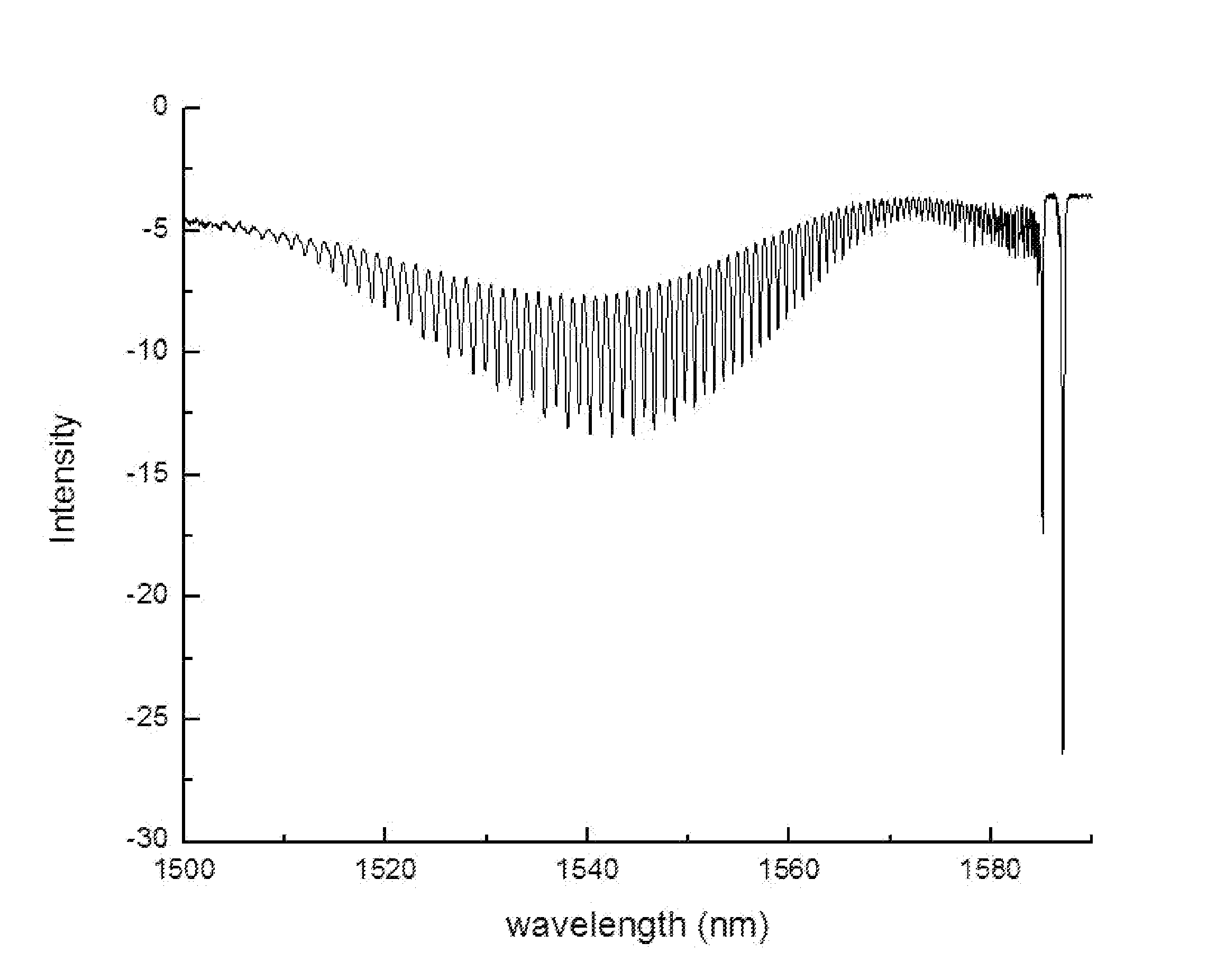
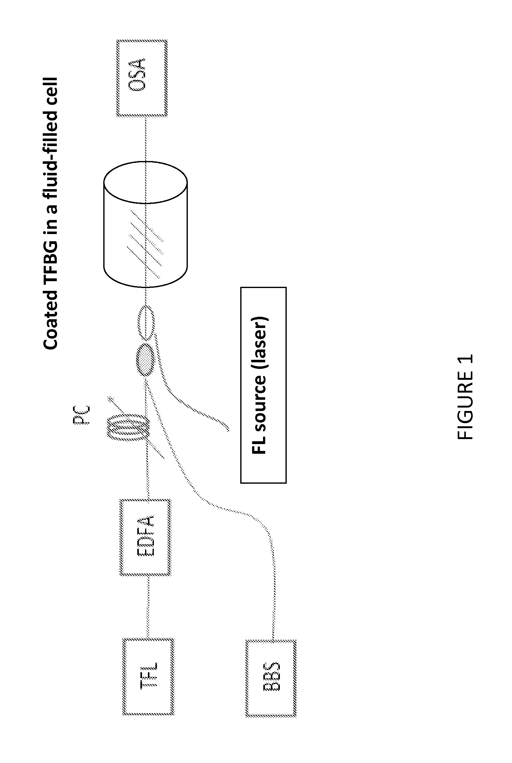
[0071]A TFBG fiber with particulate coating was manufactured according to Examples 1 and 2. A near-infrared tunable laser (TL) was tuned to the maximum absorption of the TFBG. FIG. 3 shows that maximum absorption occurs at a wavelength of approximately 1540 nm. The fiber amplifier (EDFA) was set to increase the power to any desired level between 1 mW and 1 W. For the example, the TFBG fiber with particulate coating was placed in a glass capillary tube with an inner diameter of 1 mm. The capillary was filled with water. A conventional electrical thermocouple was inserted in the capillary to measure the temperature of the liquid adjacent to the grating. The near-infrared tunable laser was set to 1540 nm and the EDFA varied the output power from 0 mW to 500 mW. As demonstrated in FIG. 4, temperatures of the order of 90° C. may be achieved with less than 1 W of optical power in the fiber. (FIG. 1, shows an illustrative example diagrami...


PUM

PropertyMeasurementUnit
Lengthaaaaaaaaaa
Fractionaaaaaaaaaa
Fractionaaaaaaaaaa

Abstract

The present invention provides, in addition to other things, methods, systems, and apparatuses that involve the use of an optical fiber with grating and particulate coating that enables simultaneous heating; optical detection; and optionally temperature measurement. Methods, systems, and apparatuses of the present invention may be used in many applications including isothermal and/or thermal cycling reactions. In certain embodiments, the present invention provides methods, systems, and apparatuses for use in detecting, quantifying and/or identifying one or more known or unknown analytes in a sample.

Description

RELATED APPLICATIONS[0001]This application claims the benefit of U.S. Provisional Application No. 61 / 662,212, filed on Jun. 20, 2012, the disclosure of which is incorporated herein by reference.BACKGROUND[0002]Optical fibers may be used to transport significant power in the form of guided electromagnetic radiation over long distances with little loss. For example, fibers for long-distance communications have a propagation loss lower than 0.3 dB / km. Typically, power exits the end of the fiber. It is possible to multiplex several light beams inside an optical fiber, and therefore use a single fiber for both heating and exciting fluorescence at its output end. In these cases, the exit surface of light is limited by the cross-section of the fiber (which typically has a diameter between 8 μm and 100 μm).[0003]U.S. Patent Application Number 2009 / 0263072 (the entire contents of which are incorporated herein by reference) describes a sensor, comprising: a sensing surface exposed to the medi...

Claims


Application Information

Patent Timeline
IPC IPC(8): G02B6/02G01N21/65G01N21/64
CPCG02B6/02057G01N21/64G01N21/645G01N2021/6484G01N21/658G01N2201/08G01N21/65G01N21/648G01N21/7743G01N2021/6432G01N2021/6441G02B6/02138G02B6/02142G02B6/0229
Inventor ALBERT, JACQUESIANOUL, ANATOLIBIALIAYEU, ALIAKSANDRBOTTOMLEY, ADAM
Owner SPARTAN BIOSCIENCE INC
Why Eureka
Try Eureka