Therapeutics dispensing device and methods of making same

a technology of therapeutics and dispensing devices, applied in the field of controlled release of therapeutics, can solve the problems of affecting the whole system, prone to injury, desiccation, pro-inflammatory stimuli, etc., and achieve the effect of prolonging the tim

Inactive Publication Date: 2015-07-09
BAYLOR COLLEGE OF MEDICINE +1
View PDF5 Cites 19 Cited by
  • Summary
  • Abstract
  • Description
  • Claims
  • Application Information

AI Technical Summary

Benefits of technology

[0036]Embodiments of the present disclosure satisfy a long-felt need in the art to provide a controlled release ocular drug delivery syst

Problems solved by technology

Treatment of an injury, diseases and inflammations with pharmaceuticals, e.g., drugs, often involve subjecting the whole system to the toxicity and/or adverse effects of those pharmaceuticals rather than just the injured site.
While localized drug delivery devices and methods are presently available, there remain several limitations to these approaches.
The smooth and wet mucosal surface of the eye, unlike other mucosal epithelia, is directly exposed to the external environment and is prone to injury, desiccation, and pro-inflammatory stimuli.
Because of the impervious nature of the ocular surface and lacrimal clearance, targeting the drug to the appropriate site of action is usually one of the greatest challenges in drug delivery (Gipson, 2007; Singh et al., 2011; Gaudana et al., 2008).
For most of the drugs, the pharmacokinetics and efficacy is well understood, however, delivery of the drug to the target site in a therapeutically effective concentration for a stipulated period of time is the challenge.
However, ocular surface barriers can limit the drug absorption and its bioavailability in the eye.
The major disadvantage of these conventional dosage forms is that they exhibit extremely low bioavailability.
Systemically administered medications, in general, have limited ocular penetration and may require high peripheral drug levels with the potential of toxicity.
Ocular or periocular injection of medication is traumatic and invasive, is rapidly diluted, and may require repeat procedures for adequate drug levels.
Lipophilic corneal epithelium is the rate limiting barrier for the diffusion of highly hydrophilic drugs, while partitioning from the corneal epithelium to the hydrophilic stroma is rate limiting for highly hydrophilic drugs that determines corneal permeability.
Improving the bioavailability by increasing the drug permeability and absorption in the eye is a great challenge.
However, due to the presence of blood capillaries and lymphatics in the conjunctiva, most of the drug will be lost into the systemic circulation, thereby lowering ocular bioavailability.
Because of the systemic drug absorption following conjunctival uptake even substantial enhancement of the drug residence times by the ocular insert drug delivery systems in the conjunctival sac may not always result in significant improvements in ocular drug absorption (Newell, 1986; Ahmed et al., 1987).
Systemic absorption of ocularly applied drugs is often nearly complete and could lead to systemic side effects varying from mild to life-threatening events.
Clinical administration of a topically applied drug is often limited by its ocular/sys

Method used


Image

  • Therapeutics dispensing device and methods of making same
  • Therapeutics dispensing device and methods of making same
  • Therapeutics dispensing device and methods of making same

Examples


example 1

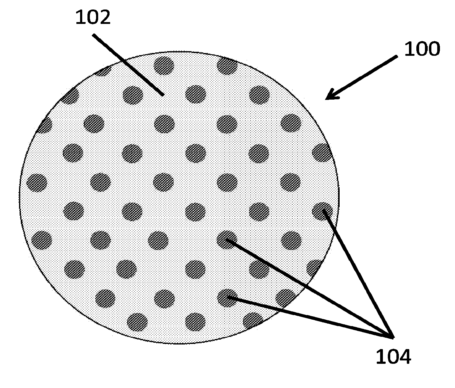
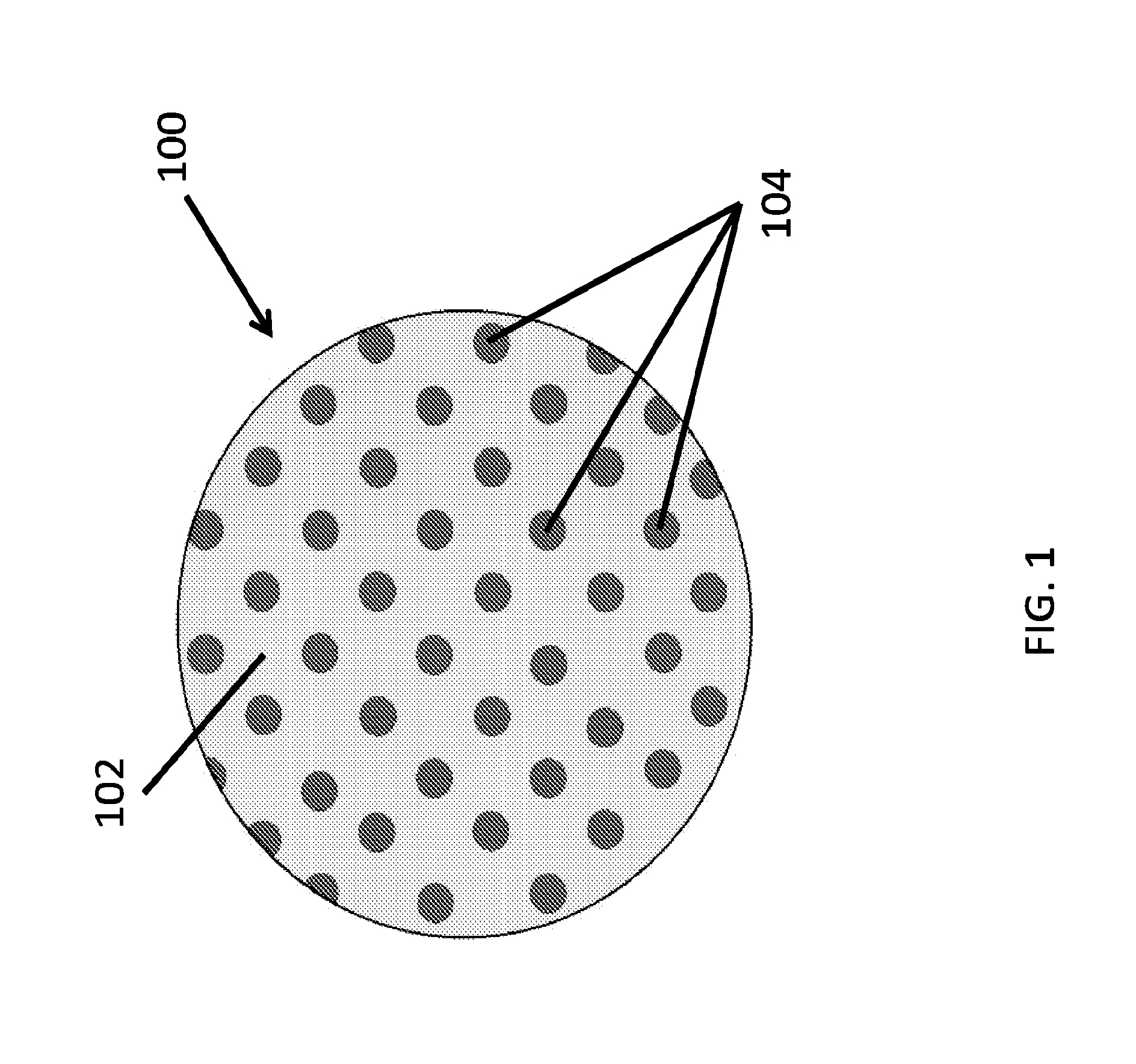
Fabrication of Polyvinyl Alcohol Microwafers

[0152]A clear polyvinyl alcohol (PVA) solution (15% w / v in water, 5 ml) was transferred with a pipette onto a PDMS template (3″ diameter) containing circular pillars (e.g., of 500 nm diameter and 500 nm height). The PVA solution was evenly spread to form a thin film completely covering the PDMS template and kept in an oven at 70° C. for 30 min. This step resulted in the formation of a thin and mechanically strong PVA template. The PVA template was peeled away from the PDMS template. The obtained PVA template was ˜3″ in diameter, contained circular wells (e.g., of 500 nm diameter and 500 nm depth). The PVA template was examined under a bright field reflectance microscope to determine its structural integrity.

example 2

Fabrication of Polyacrylic Acid Microwafers

[0153]A clear polyacrylic acid (PAA) solution (10% w / v in ethanol, 5 ml) was transferred with a pipette onto a PDMS template (3″ diameter) containing circular pillars (e.g., of 500 nm diameter and 500 nm height). The PAA solution was evenly spread to form a thin film completely covering the PDMS template and kept in an oven at 70° C. for 30 min. This step resulted in the formation of a thin and mechanically strong PAA template. The PAA template was peeled away from the PDMS template. The obtained PAA template was ˜3″ in diameter, contained circular wells (e.g., of 500 nm diameter and 500 nm depth). The PVA template was examined under a bright field reflectance microscope to determine its structural integrity.

example 3

Fabrication of Polyhydroxyethylmethacrylate Microwafers

[0154]A clear polyHEMA solution (12% w / v in ethanol, 5 ml) was transferred with a pipette onto a PDMS template (3″ diameter) containing circular pillars (e.g., of 500 nm diameter and 500 nm height). The PVA solution was evenly spread to form a thin film completely covering the PDMS template and kept in an oven at 70° C. for 30 min. This step resulted in the formation of a thin and mechanically strong polyHEMA template. The polyHEMA template was peeled away from the PDMS template. The obtained polyHEMA template was ˜3″ in diameter, contained circular wells (e.g., of 500 nm diameter and 500 nm depth). The polyHEMA template was examined under a bright field reflectance microscope to determine its structural integrity.


PUM

PropertyMeasurementUnit
Timeaaaaaaaaaa
Depthaaaaaaaaaa
Surface areaaaaaaaaaaa

Abstract

A therapeutics delivery system, and methods of making and using same, are disclosed for environments that rapidly clear any injected therapeutics, such as a patient's eye. The therapeutics delivery system releases the drug in a therapeutically effective concentration for a desired duration of time with a predefined drug kinetics. In one embodiment, the embodiments of the present disclosure release a therapeutically effective concentration for a longer time period than other delivery systems, for instance from a day to a week. Certain embodiments comprise a therapeutics dispensing device comprising a biodissolvable hydrogel matrix for long term drug release that allows the device to be placed directly at the injured site, e.g., onto the surface at or near the injury, and retained there rather than through injection, whether locally or systematically.

Description

[0001]This application claims priority to U.S. Provisional Patent Application Ser. No. 61 / 679,908, filed Aug. 6, 2012, and claims priority to U.S. Provisional Patent Application Ser. No. 61 / 775,891, filed Mar. 11, 2013, both of which applications are incorporated by reference herein in their entirety.[0002]This invention was made with government support under R01 EY011915-14 awarded by the National Eye Institute. The government has certain rights in the invention.TECHNICAL FIELD[0003]The present disclosure generally relates to controlled release of therapeutics in an individual, such as delivery of therapeutics locally through a dissolvable hydrogel matrix. In particular embodiments, the field of the invention includes at least cell biology, molecular biology, biomedical engineering, and medicine.BACKGROUND OF THE DISCLOSURE[0004]Treatment of an injury, diseases and inflammations with pharmaceuticals, e.g., drugs, often involve subjecting the whole system to the toxicity and / or adve...

Claims


Application Information

Patent Timeline
IPC IPC(8): A61F9/00B29C33/38B29C39/02
CPCA61F9/0017B29C39/02B29C33/3842B29L2031/712A61F2240/005A61F2310/00383A61F2210/0004A61F2250/0068A61K9/0048A61K9/0051A61K9/7007A61K47/32A61K47/34A61K47/42A61P3/10A61P25/00A61P27/02A61P27/06A61P29/00A61P31/00
Inventor ACHARYA, GHANASHYAMPFLUGFELDER, STEPHEN C.DE PAIVA, CINTIA S.SIMPSON, JENNIFER L.
Owner BAYLOR COLLEGE OF MEDICINE
Why Eureka
Try Eureka