An NF membrane having a surface thereof charged negative is preferably used as a membrane principally aimed at separation and removal of the photoresist into the concentrate. Since the photoresist usually exists in the anionic form in the development waste or the treated solution derived therefrom, the use of the NF membrane having a surface thereof charged negative improves the rejection against the photoresist and hardly brings about
fouling (
contamination) of the NF membrane otherwise attributed to attachment thereto of the photoresist. In this case, an anionic surfactant can also be effectively separated and removed into the concentrate when the development waste or the treated solution derived therefrom contains the anionic surfactant. Further, in general, the NF membrane is also capable of separating and removing a
nonionic surfactant, a cationic surfactant, etc. into the concentrate. Needless to say, an NF membrane having a surface thereof charged positive or a neutral NF membrane may also be used in accordance with properties of the development waste or the treated solution derived therefrom (e.g., the kind of surfactant, if contained therein).
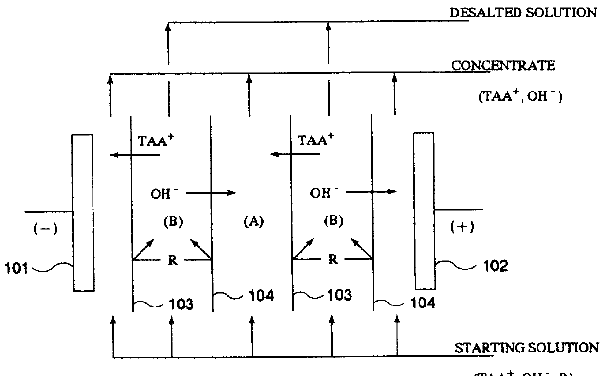
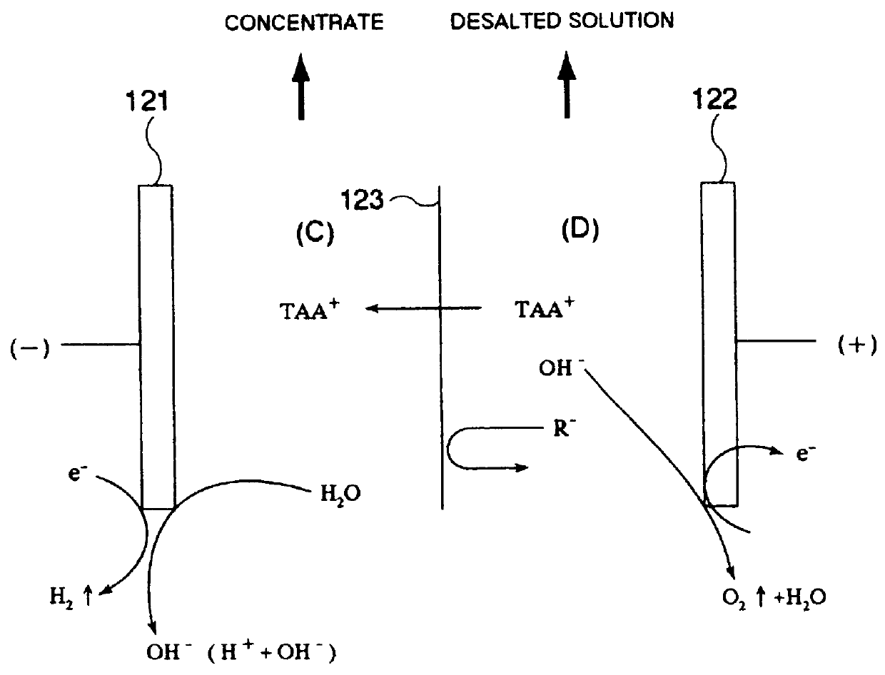
For example, a concentrate having TAA ions concentrated therein and obtained through the concentration treatment step (a) of treating the development waste by at least one concentration method selected from among
reverse osmosis membrane treatment,
evaporation, electrodialysis, and
electrolysis may be used as the treated solution derived from the development waste because the TAA
ion concentration of the development waste is usually lowered with rinsing water and the like. In this case, however, care must be taken because the operating pressure of a nanofilter rises as the TAAH concentration increases and because the
life span of the NF membrane is shortened as the pH value rises. Where a plurality of such concentration methods are used in combination, the order thereof is not particularly limited and may be arbitrary. For example, when
reverse osmosis membrane treatment and / or
evaporation is followed by electrodialysis and / or electrolysis, there can be obtained advantages such as an improvement in current efficiency during electrodialysis and / or electrolysis,
miniaturization and running cost reduction of an electrodialysis and / or an electrolysis unit(s) due to a decrease in the amount of the solution to be treated therewith, lowering of a
voltage to be applied to such a unit(s), and an improvement in TAA
ion recovery (Japanese
Patent Application No. 334,800 / 1997). When the
neutralization and
solid-liquid separation step (c) and / or the
ion exchange treatment step (d) is also taken in this case, this evaporation and / or reverse
osmosis membrane treatment step may be taken at any stage, e.g., at first, later or between both. Additionally stated, either
condensed water obtained by evaporation or permeate water obtained by reverse
osmosis membrane treatment does not substantially contain the photoresist and TAA ions to be able to serve as process water or the like. In passing, in the case of reverse
osmosis membrane treatment, the solution to be treated thereby preferably has a pH value of 9 to 12 from the standpoint of minimizing the deterioration of a reverse osmosis membrane.
When a photoresist-containing solution such as the development waste is brought into contact with the anion exchange resin, the photoresist can be adsorbed on the anion exchange resin, whereby the photoresist can be highly selectively removed from the solution. The reason for this is believed to be as follows: The mainstream alkali-developable photoresists are those having a novolak resin as the matrix resin. This novolak resin has a large number of
benzene rings. When a
styrene type anion exchange resin having
benzene rings or the like resin in particular is, for example, used as the anion exchange resin, it is believed that the photoresist can be efficiently and highly selectively removed due to affinity (hydrophobic) interaction between the respective
benzene rings of the anion exchange resin and the photoresist in addition to the mutual
electrostatic interaction thereof.
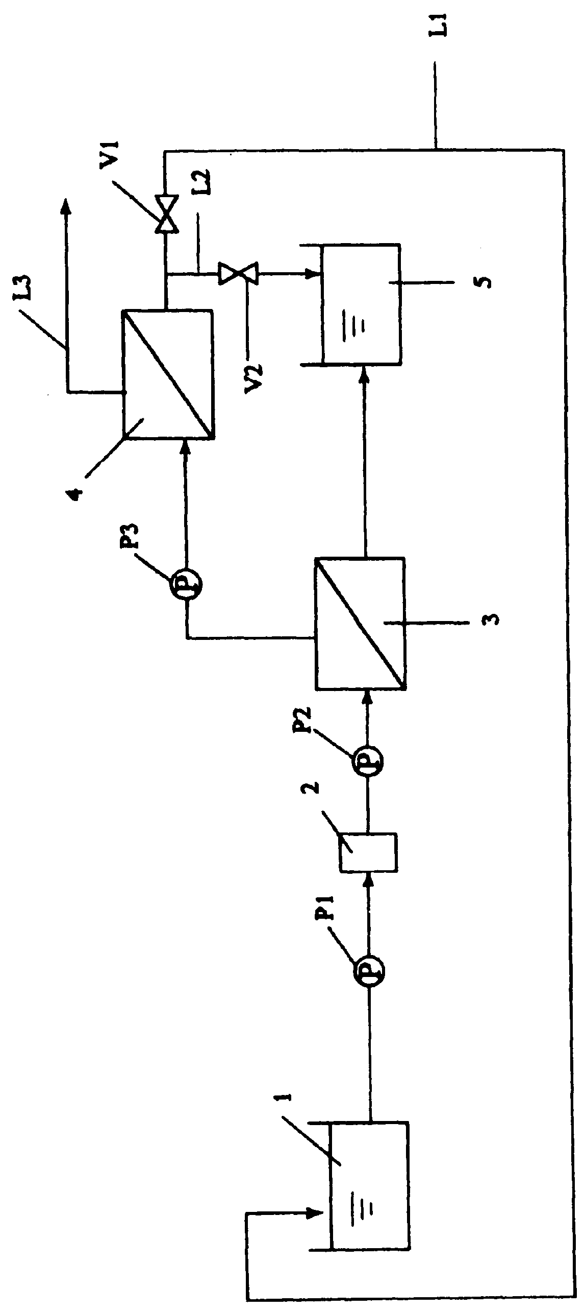
When the development waste or the treated solution derived therefrom is treated with the NF membrane, most of TAAH permeates through the NF membrane to enter the permeate, while a little, if any, photoresist permeates through the NF membrane to remain mostly in the concentrate wherein the photoresist is therefore concentrated. Further, a considerable amount of impurities such as some
metal component including Fe and Al, and silica, which are hard to remove by
ion exchange treatment, can be removed into the concentrate because they little permeate through the NF membrane. Accordingly, the permeate obtained only by separation treatment with the NF membrane may be used as such, for example, when the
impurity concentration of the original development waste is low, or when the use of the rejuvenated developer is such that even a low purity thereof is tolerable.
When the rejuvenated developer is to be reused in the processes for production of electronic parts such as
semiconductor devices,
liquid crystal displays and printed boards, in which impurities must be avoided to an extreme extent, or the like processes, however, a high purity and / or
high concentration of the rejuvenated developer is required, so that this permeate is usually subjected to a variety of refining and / or concentration step(s) at later stage. Nevertheless, use of the permeate stripped of most of impurities by separation treatment with the NF membrane can decrease the load of impurities in the later step(s) such for example as the
ion exchange treatment, electrodialysis and / or electrolysis step to reduce the refining cost. Additionally stated, the step of separation treatment with the NF membrane is inexpensive and easy of operation.
Since the permeate obtained by separation treatment with the NF membrane (hereinafter often referred to as the "NF permeate") is a TAAH solution having a considerably high purity, it may advantageously be passed as a concentrating liquid (liquid for
recovery therein of TAAH) for electrodialysis or electrolysis through the concentrating
cell(s) of an electrodialysis or electrolysis unit, while the concentrate obtained by separation treatment with the NF membrane (hereinafter often referred to as the "NF concentrate") may be passed as a starting solution (solution to be depleted of TAAH) for electrodialysis or electrolysis through the desalting
cell(s) of the electrodialysis or electrolysis unit, if the NF concentrate contains a considerable amount of TAAH remaining therein. In this case, since the NF permeate is used instead of (ultra)pure water as the concentrating liquid, the amount of
wastewater discharged as the desalted waste can advantageously be decreased. Further, the amount of TAAH transferred into the concentrating liquid by electrodialysis or electrolysis can advantageously be decreased to be able to reduce the running cost and miniaturize the unit.

