For example, in case where a developer is used for a long period, the carrier surface is soiled with so-called "spent toner" which is a portion of toner melt-sticking and filming onto the carrier surface and is useless for development, whereby the developer is deteriorated and the developed images are accompanied with
image quality deterioration.
Generally, if the carrier has an excessively large true
specific gravity, the developer suffers from a large load when the developer is formed in a layer of a prescribed thickness on the developing sleeve or when the developer is stirred in the developing device.
As a result, during the use of the developer for a long period, the developer is liable to be deteriorated by (a) toner filming, (b) carrier breakage and (c) toner deterioration, thus resulting in developed images with inferior
image quality.
Further, if the carrier particle size is excessively large, the developer receives a large load similarly as above, thus being liable to suffer from the above-mentioned difficulties (a)-(c) and deteriorate the developer.
Further, the developed images are liable to cause (d) a lowering in thin-line reproducibility.
Accordingly, a carrier liable to cause the difficulties (a)-(c) requires a periodical exchange of the developer which is uneconomical.
Further, only the carrier particle size is reduced while the toner particle size remains at constant, the toner is provided with a broad distribution of charge and is particularly excessively charged ("charge-up") in a low
humidity environment, thus being liable to cause a phenomenon of toner scattering onto the non-image portion ("
fog").
However, this type of carrier has a difficulty that it has a small saturation
magnetization relative to its particle size unless it contains a large proportion of magnetic material, thus being liable to cause carrier attachment onto the electrostatic image-bearing member, so that it is necessary to install a mechanism for developer replenishment or attached
carrier recovery within the image forming apparatus.
On the other hand, a magnetic fine particle dispersion-type resin carrier containing a large proportion of magnetic material is liable to have a weaker
impact resistance because of an increased amount of the magnetic material relative to the binder resin, so that (g) the magnetic material is liable to fall off (or be liberated from) the carrier when the developer is formed in a layer of a prescribed thickness, thus resulting in deterioration of the developer.
Further, a magnetic fine particle-dispersion-type resin carrier containing a large proportion of magnetic material is liable to have a lower resistivity because of an increased amount of magnetic material having a low resistivity, so that (h) the bias
voltage applied for development is liable to be leaked to result in inferior images.
However, the resin-coated carrier is also accompanied with a difficulty that a carrier having a
high resistivity due to a large amount of
coating resin is liable to cause a toner charge-up in a low
humidity environment.
Further, if the
resin coating amount is less, the
resultant carrier is caused to have a lower resistivity, thus being liable to cause inferior images due to leakage of the developing bias
voltage.
Further, in case where a certain
coating resin is used, even if a carrier coated with the resin exhibits a numerically appropriate resistivity, the carrier can cause inferior images due to leakage of the developing bias
voltage, or another carrier can cause toner charge-up in a low
humidity environment.
However, the carriers of JP-A 4-198946 and JP-A 5-72815 cannot have a high coating rate because of a restriction in production process, thus leaving problems regarding little environmental dependence and sufficient toner-charging ability.
Further, in the developer proposed, the spent toner attachment is liable to occur on the carrier in case of
copying of a toner-consuming large area image on a large number of sheets, thus being liable to cause toner charge fluctuation.
If the
residual magnetization .sigma..sub.r of the magnetic carrier exceeds 20 Am.sup.2.kg, the exchange between the two-component developer on the developer-carrying member and the two-component developer in the developer container is not uniformly performed, so that the toner charge-up or toner charge fluctuation is liable to occur.
If the magnetic carrier has a resistivity below 5.times.10.sup.11
ohm.cm, a
charge injection from the developer-carrying member to the electrostatic image-bearing member is liable to occur in the developing region, thus being liable to cause carrier attachment onto the electrostatic image-bearing member, disorder of electrostatic images and image defects.
On the other hand, if the magnetic carrier has a resistivity exceeding 5.times.10.sup.15
ohm.cm, the charge generated by triboelectrification with the toner cannot be leaked therefrom and the toner charge is liable to be excessively increased, thus being liable to cause a
image density lowering and
fog due to the toner charge-up, particularly in low humidity environment.
If the mol ratio is below 1, it is difficult to form the particles of the resin or only possible to form resin particles having a weak
mechanical strength.
On the other hand, if the
aldehyde compound is excessive, the content of non-reacted
aldehyde remaining in the
aqueous medium after the reaction is liable to increase.
This is because, the
fluorine atoms contained in this part adjacent to the
ester bond (COO) are liable to make the fluoro-
alkyl unit-containing ester group less flexible, i.e., fragile.
In excess of 3.0 g / cm.sup.3, a large shearing force is caused within the developer whereby the carrier is liable to be soiled with spent toner or suffer from peeling of the coating resin.
If the magnetic carrier has a
sphericity exceeding 130, the
resultant developer is liable to have inferior flowability, whereby the developer is caused to show a lower triboelectric charging ability to the toner and is liable to form a non-uniform shape of magnetic
brush, thus failing to provide high-quality images.
%,
fog and toner scattering in the apparatus are liable to occur, and the life of the developer is liable to be shortened.
If the ratio is below 0.1, it becomes difficult to well charge the toner, and fog and toner scattering in a
high humidity environment are liable to occur.
On the other hand, in excess of 0.3, the toner is liable to have an excessively high charge especially in a low humidity environment, thus being liable to cause a lowering in
image density and fog.
If the toner has a weight-average particle size (D4) exceeding 9.9 .mu.m, the toner particles for developing electrostatic latent images become so large that development faithful to the latent images cannot be performed even if the magnetic force of the magnetic carrier is lowered, and extensive toner scattering is caused when subjected to electrostatic transfer.
If D4 is below 3 .mu.m, the toner causes difficulties in
powder handling characteristic.
If the cumulative amount of particles having sizes of at most a half of the number-average particle size (D1) exceeds 20% by number, the triboelectrification of such fine toner particles cannot be satisfactorily effected to result in difficulties, such as a broad triboelectric charge distribution of the toner, charging failure (occurrence of reverse charge fraction) and a particle
size change during continuous
image formation due to localization of toner particle sizes.
If the cumulative amount of particles having sizes of at least two times the weight-average particle size (D4) exceeds 10% by volume, the triboelectrification with the magnetic carrier becomes difficult, and faithful
reproduction of latent images becomes difficult.
If the Mw / Mn of the
wax exceeds 1.45, the toner is liable to have inferior fluidity, thus resulting in gloss irregularity of the fixed images, and is further liable to have a lower transferability and soil the contact charging member.
If the
wax melting point exceeds 150.degree. C., an excessively large energy is required in the case of toner production through the pulverization process, and in the case of toner production through the
polymerization process, the uniform dispersion of the
wax in the binder resin requires a larger apparatus because of an increased
viscosity, and the inclusion of a large amount of wax becomes difficult.
If the wax melt-
viscosity is below 1 mPa.sec, the resultant toner is liable to be damage by a shearing force acting between the toner and the carrier in the two-component developer
system, and the embedding of the external additive at the toner particle surface and the toner breakage are liable to occur.
If the wax melt-
viscosity exceeds 50 mPa.sec, the disperse phase during toner production through the
polymerization process is caused to have a high viscosity, so that it becomes difficult to obtain a
small particle size toner of uniform particle sizes, thus being liable to result in a toner having a broad
particle size distribution.
A wax having Mw below 200 or Mn below 150 results in a toner exhibiting poor anti-blocking property.
If the wax amount is too low the anti-offset effect is liable to be inferior.
If the wax amount is excessively large, the resultant toner is liable to cause melt-sticking onto the photosensitive drum and the developing sleeve distribution is liable to be formed.
The
emulsion polymerization process as represented by the
soap-free polymerization is effective for providing toner particles having a relatively narrow
particle size distribution, but the used emulsifier and polymerization initiator terminal are liable to be present at the toner particle surfaces, thus resulting in an inferior environmental characteristic.
In case of a toner not having such an
enclosure structure, the wax cannot be dispersed uniformly to result in a toner having a broad particle size distribution and liable to cause melt-sticking onto the apparatus members.
If the
temperature difference exceeds 100.degree. C., the low-temperature fixability of the resultant toner may be impaired.
If the
glass transition temperature is below 40.degree. C., the resultant toner is provided with only a low storage stability and inferior flowability, thus failing to provide good images.
If the average particle size exceeds 0.2 .mu.m, the flowability-improving effect is reduced, whereby the
image quality can be lowered due to inadequate developing or transfer performance in some cases.
Silicone oil having a lower viscosity because of too low a molecular weight can generate a volatile matter during a heat treatment.
On the other hand,
silicone oil having a higher viscosity because of too high a molecular weight makes difficult a surface treatment therewith.
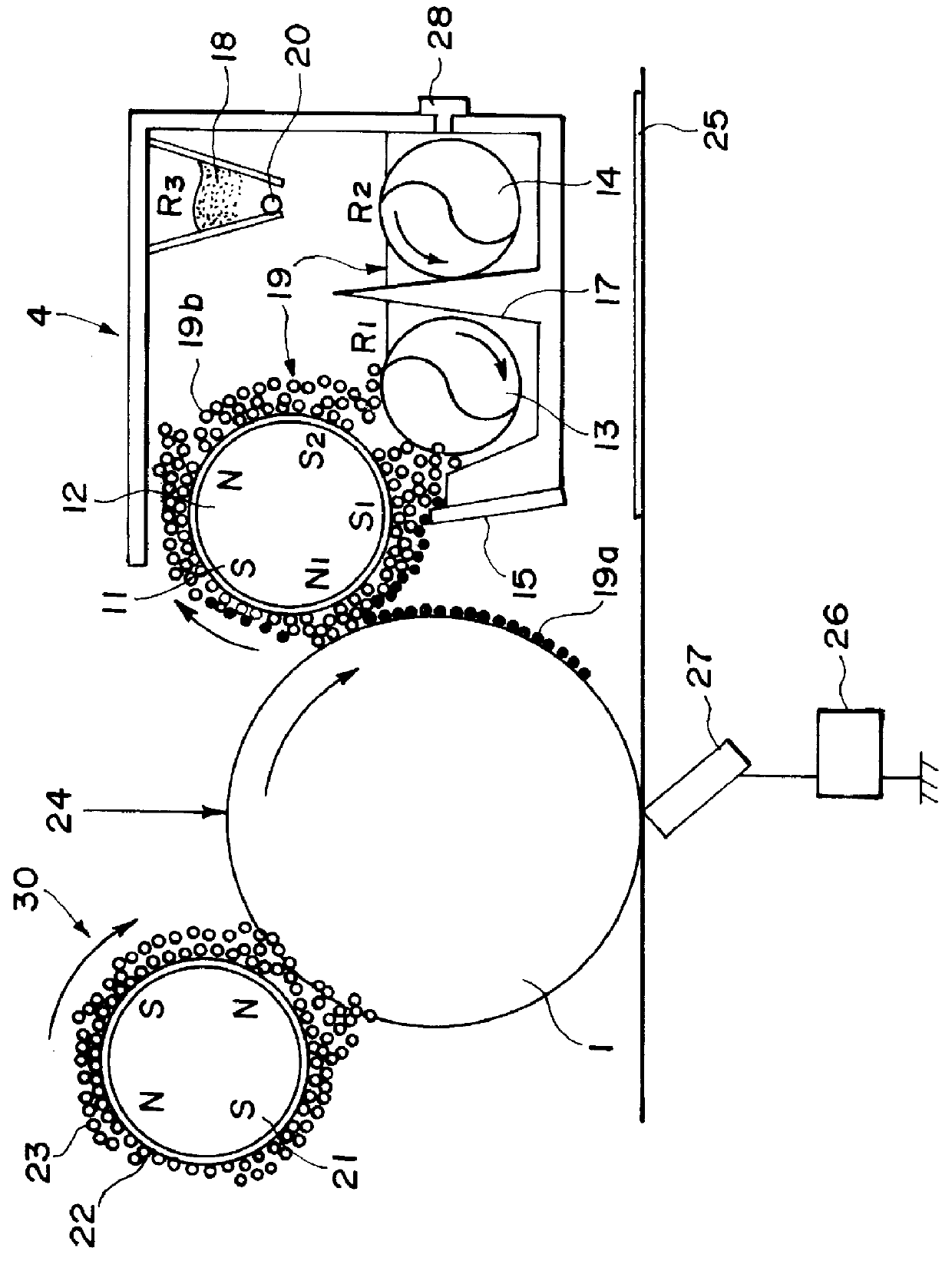
Below 100 .mu.m, the developer supply is liable to be insufficient to result in a lower image density.
Above 1000 .mu.m, lines of magnetic forces exerted by a magnetic pole S.sub.1 are broadened to provide a magnetic
brush of a lower density, thereby being liable to result in images with an inferior dot reproducibility and carrier attachment due to weakening of a constraint force acting on the magnetic carrier.
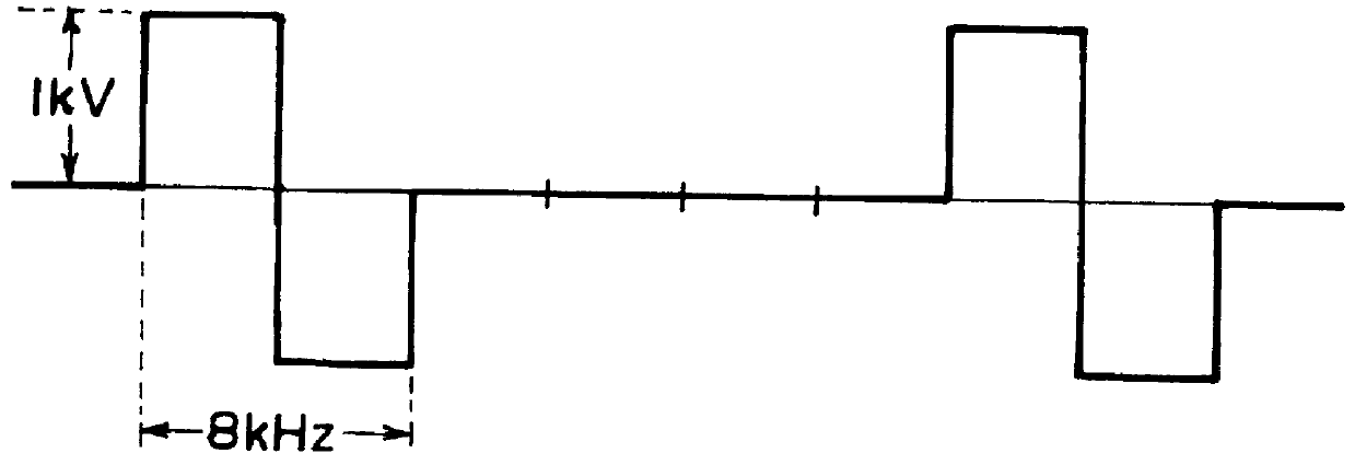
If the application voltage is below 500 volts it may be difficult to obtain a sufficient image density and fog toner on a non-image region cannot be satisfactorily recovered in some cases.
Above 5000 volts, the
latent image can be disturbed by the magnetic
brush to cause lower image qualities in some cases.
The frequency can affect the process, and a frequency below 500 Hz may result in
charge injection to the carrier, which leads to lower image qualities due to carrier attachment and latent image disturbance, in some cases.
Above 10000 Hz, it is difficult for the toner to follow the
electric field, thus being liable to cause lower image qualities.
If the developing nip is narrower than 3 mm, it may be difficult to satisfy a sufficient image density and a good dot reproducibility.
If broader than 8 mm, the developer is apt to be packed to stop the movement of the apparatus, and it may become difficult to sufficiently prevent the carrier attachment.
If the gap is below 300 .mu.m, the gap may be plugged with the magnetic carrier to result in an irregularity in the developer layer and a difficulty in applying an amount of toner required for performing good development, thus being liable to result in images with a
low density and much irregularity.
Above 1000 .mu.m, however, the amount of developer applied onto the developing sleeve 11 is increased so that it becomes difficult to effect a prescribed developer
layer thickness regulation, whereby the amount of magnetic carrier attachment onto the photosensitive drum 1 is increased and the circulation of the developer and the regulation of the developer by the regulating blade 15 are weakened to provide the toner with a lower triboelectric charge, leading to foggy images.
If the abutting pressure is below 2.94 N / m, the conveyance deviation or transfer failure of transfer material is liable to occur.

