Plating processes utilizing high intensity acoustic beams

a technology of acoustic beams and plating processes, which is applied in the direction of nuclear engineering, electric/magnetic/electromagnetic heating, and can solve the problems of unfavorable tooling cost performance, non-uniform thickness of plating, and obstructing plating, etc., to improve the selective plating process, and improve the effect of plating

Inactive Publication Date: 2002-04-09
NAT AERONAUTICS & SPACE ADMINISTATION U S AS REPRESENTED BY THE +1
View PDF3 Cites 64 Cited by
  • Summary
  • Abstract
  • Description
  • Claims
  • Application Information

AI Technical Summary

Benefits of technology

The invention is directed to a system and a method for improving selective plating processes by using direct beams of high intensity acoustic waves to create non-linear effects for improving the plating process. The invention improves selective plating of a surface on an object which in one embodiment is immersed in a plating solution, and in another embodiment is suspended above the plating solution.

Problems solved by technology

The bubbles, typically hydrogen, form as a consequence of the deposition process and the bubbles will obstruct plating and create pinholes and non-uniform thickness in the plating.
Special tanks and customized anodes may be needed which disadvantageously raises the tooling cost to perform the plating.
This practice is particularly costly for precious metal plating.
Another disadvantage occurring in prior art electroplating is that as plating takes place the plating solution is continuously creating concentration gradients.
For complex objects with isolated cavities simple agitation cannot provide complete uniformity.
Another disadvantage is that the formation of hydrogen or oxygen gas is a byproduct of the process.
Unfortunately, for complex objects the bubbles dislodged in one location may be trapped in another location.
A simple tape mask is applied manually and can be very labor intensive, but suitable for low volume production or repairs.
The typical photolithographic or photomask is suitable for high volume but requires a photo tool to be used which is costly to produce.
Some masking chemicals are toxic, carcinogenic or create compounds that are toxic.
Each stage creates waste that may be toxic and poses special handling and disposal costs.
The photomasks also have a limited shelf life.
The material may be wasted even before it is used due to inadvertent exposure to light or heat and the simple degradation in storage.
The new aqueous materials are more acceptable from a health consideration but they are not as sturdy as hydrocarbon types.
When the plating solution deposits the metal, it also becomes more basic and in some cases will attack the photomask and ultimately result in a flawed or damaged product.
One of the main disadvantages of pulse plating is that it only reverses the process and there is a slight difference between deposition rate and extraction rate which may lead to non-uniform thickness of the plating.
The electroless plating does not rely on electric fields and therefore is harder to regulate.
Since electroless plating does not rely on externally applied electric fields, it is harder for the user to regulate the process.
Unlike electroplating the electroless plating process cannot be easily turned "ON" and "OFF" by application of electric power.
For objects, such as electronic circuit boards, the failure of a mask will cause insulator surfaces to become conductive which may disadvantageously lead to short circuits.
Brush plating is a selective electroplating process that is usually done by hand and thus is used mostly for repairs, very low production volume or plating in the field due to the limited provisions needed.
However, this process is prone to spills and brings the user in close contact with corrosive, reactive and even toxic materials.
The manual application disadvantageously requires a skill to achieve uniform and consistent results and also masking is often required.
Because of the difficulty controlling the behavior of the liquid once it contacts the surface, the process normally requires a mask for selective plating.
This process also disadvantageously requires masking for selective plating.
The isolated droplets may be charged, but will not sustain a continuous current between the source and the object.
However, masking is disadvantageously required for selective plating.
Further, the atomization process creates a mist of toxic, corrosive or reactive material that may coat other objects and may be inhaled by workers.

Method used


Image

  • Plating processes utilizing high intensity acoustic beams
  • Plating processes utilizing high intensity acoustic beams
  • Plating processes utilizing high intensity acoustic beams

Examples


Embodiment Construction

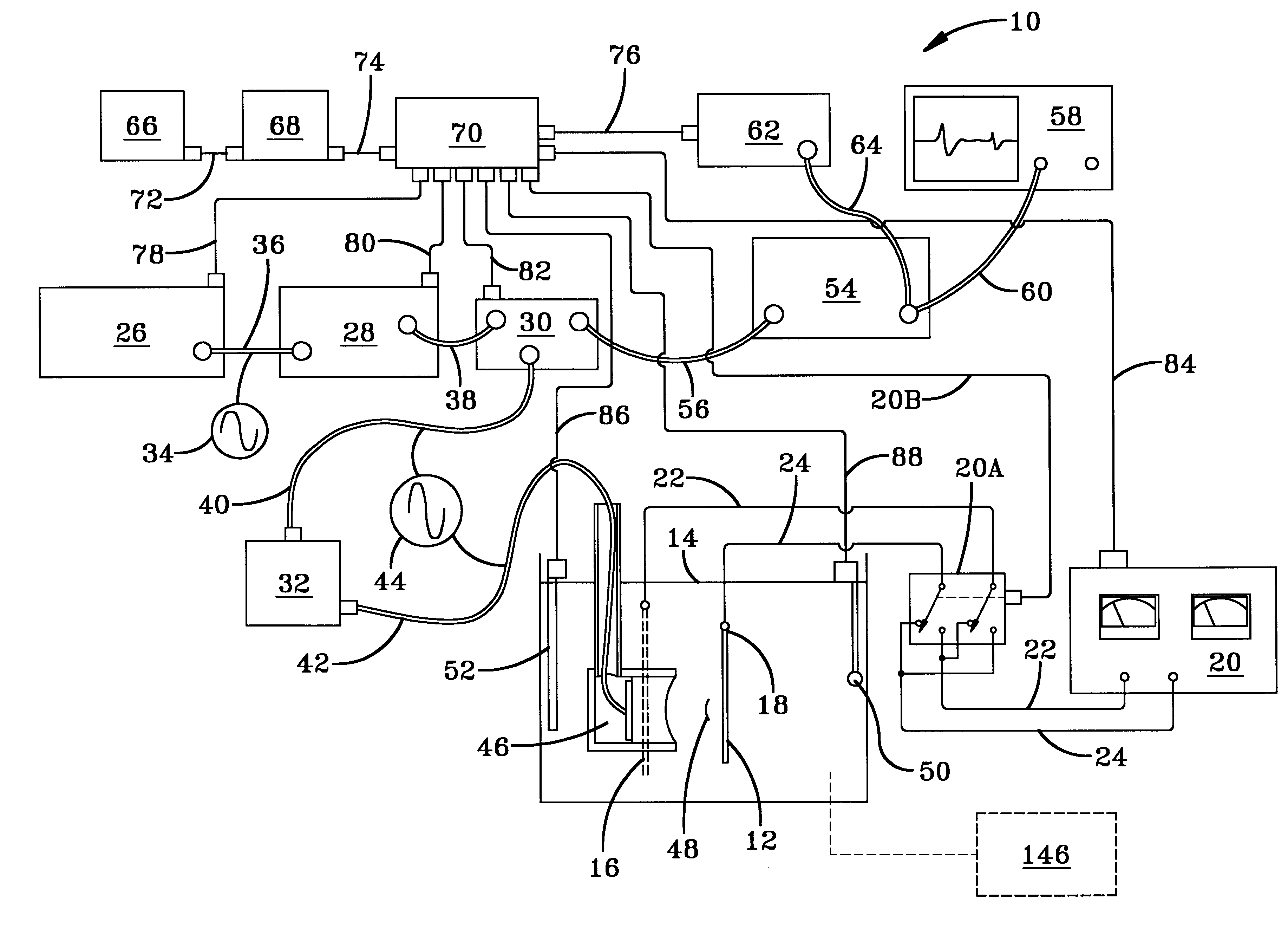
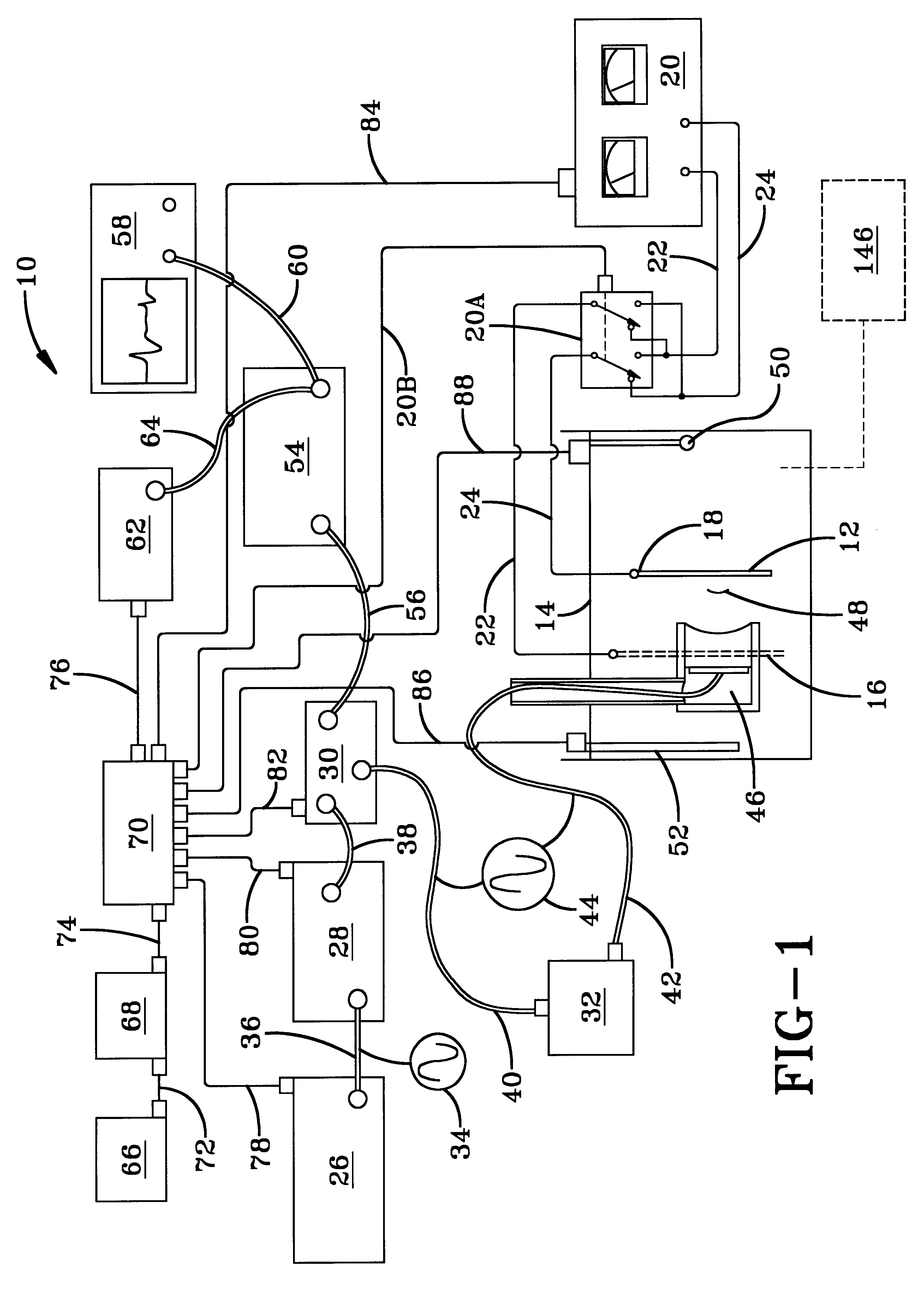
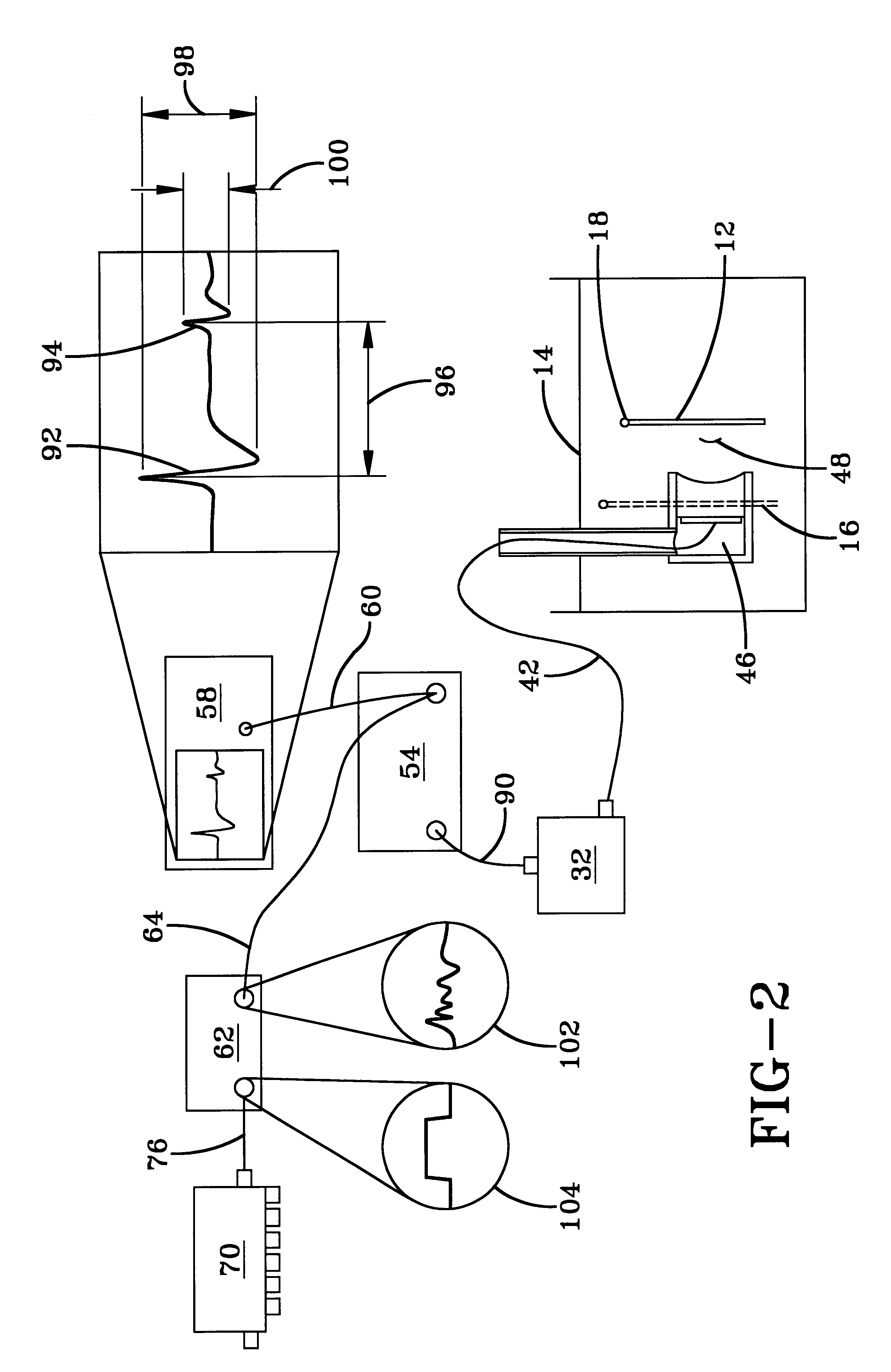
FIG. 3(A) shows an immersion electroplating process enhanced by using acoustic waves in accordance with the practice of the present invention. An object 12 to be plated and a single physically focused transducer 46 is immersed in a plating tank 14 filled with a plating solution 108. The transducer 46 emits acoustic waves through a buffer 46A to a concave acoustic lens 46B. The beam of waves, generally identified by reference number 48, is focused at an area on the surface of the object 12. The object 12 shown is a simple flat panel of conductive or partially conductive material, such as a circuit board. A simple focused transducer 46 is shown, but a phased array or a plurality of transducers may also be used in a manner to be further described hereinafter with reference to FIG. 6. An electrical conductor 42, previously described in FIG. 1 as a coaxial cable, is connected to the back side of the transducer element 46C. The ground or return side of transducer 46 is connected to the gr...


PUM

PropertyMeasurementUnit
frequencyaaaaaaaaaa
poweraaaaaaaaaa
output impedanceaaaaaaaaaa

Abstract

A system and a method for selective plating processes are disclosed which use directed beams of high intensity acoustic waves to create non-linear effects that alter and improve the plating process. The directed beams are focused on the surface of an object, which in one embodiment is immersed in a plating solution, and in another embodiment is suspended above a plating solution. The plating processes provide precise control of the thickness of the layers of the plating, while at the same time, in at least some incidents, eliminates the need for masking.

Description

This invention relates to plating processes and, more particularly, to selected plating processes each of which utilizes directed beams of high intensity acoustic waves to create non-linear effects that alter and improve each of the plating processes.BACKGROUND OF THE ARTThe plating of objects, such as circuit boards, may be accomplished by various processes. One such process is an immersion type of selective electroplating that involves a tank filled with plating solution or electrolyte. Electrodes are placed in the tank, sometimes referred to as a plating bath, and a voltage is applied to the electrodes to set up an electric field in the tank. A power supply that has a variable voltage and amperage control is used to create the voltage between the electrodes. One electrode, called the anode, is attached to the positive terminal of a power supply. The other electrode, called the cathode, is attached to the negative or ground terminal of the power supply. The object to be plated is ...

Claims


Application Information

Patent Timeline
Patent Type & Authority Patents(United States)
IPC IPC(8): C25D5/00C25D5/20C25D5/02H05K3/24
CPCC25D5/02C25D5/20H05K3/241
Inventor OEFTERING, RICHARD C.DENOFRIO, CHARLES
Owner NAT AERONAUTICS & SPACE ADMINISTATION U S AS REPRESENTED BY THE
Why Eureka
Try Eureka