Method and apparatus for purifying polluted substances containing halogenated organic compound

a technology of halogenated organic compounds and purification methods, which is applied in the direction of water cleaning, biological water/sewage treatment, contaminated groundwater/leachate treatment, etc., can solve the problems of hepatic damage, long treatment time, and inability to easily degrade halogenated organic compounds in the natural world

Inactive Publication Date: 2004-01-20
EBARA CORP
View PDF4 Cites 13 Cited by
  • Summary
  • Abstract
  • Description
  • Claims
  • Application Information

AI Technical Summary

Problems solved by technology

These halogenated organic compounds are not easily degraded in the natural world, and sparingly soluble in water.
Thus, they tend to be accumulated in the soil and penetrated into groundwater in the contaminated area.
The halogenated organic compounds are also known to cause hepatic damage and have carcinogenicity.
Bioremediation, however, has the problems that treatment requires a long time, and the types and concentrations of substances which can be degraded are restricted, as will be described below.
However, this method has the following drawbacks: 1) Degradation reaction is unstable.
However, they are defective, for example, in that 1) growth of the microorganisms is very slow, and 2) strongly toxic intermediary metabolites are formed and accumulated during the anaerobic degradation process (Uchiyama HIROO and Yagi OSAMI, Bioscience and Industry, 1994, Vol. 52, No. 11, 879-884).
However, no dechlorination reaction was observed under conditions under which no microorganisms were cultured, particularly when a reductive atmosphere and neutral conditions were not maintained.
This method involves a problem about air injection facilities, and a risk of vaporization of the halogenated organic compounds.
The method is also impractical, since the use of high pressure air causes the problem of cost.
However, this report is silent on concrete natural substances and microorganisms.
However, this U.S. patent does not describe a reducing agent, such as reduced iron, cast iron, an alloy, or a water-soluble reducing agent.
To purify a contaminated object, such as soil, actually in situ, on the other hand, large amounts of a reducing agent and a nutrient source are mixed, thus requiring construction work.
Moreover, uniform mixing is not necessarily easy.
In addition, the conditions during kneading may affect the degradation ratio of halogenated organic compounds.
With this method, however, the pumped contaminated water cannot be reinjected unless it is purified below the concentration complying with the ban on the permeation of effluent into the ground.
Thus, it is necessary to install purification facilities on the ground, posing the problem of an increased cost.
Also, the injected normal water brings about a phenomenon of a detour formed in the flow of the contaminated groundwater.
This phenomenon poses the problem that the injected nutrient source does not thoroughly mix with the groundwater.
The standard electrode potential of less than -2400 mV is not preferred, either, because the reducing power is so strong that a hydrogen gas may be generated, posing a danger.

Method used


Image

  • Method and apparatus for purifying polluted substances containing halogenated organic compound
  • Method and apparatus for purifying polluted substances containing halogenated organic compound
  • Method and apparatus for purifying polluted substances containing halogenated organic compound

Examples


second embodiment

Next, the purification apparatus of the present invention is shown in FIG. 3. FIG. 3 is a schematic view showing a state of installation of the purification apparatus using a water soluble reducing agent as the reducing agent. As the water soluble reducing agent, there can be preferably used an organic acid or its derivative, hypophosphorous acid or its derivative, or a salt of an organic acid or hypophosphorous acid with iron, titanium, zinc, manganese, aluminum or magnesium, or a sulfide salt. As the organic acid, a carboxylic acid, a sulfonic acid, a phenolic acid, or a derivative thereof can be used preferably. Preferably used examples of the carboxylic acid are monocarboxylic acids, dicarboxylic acids, tricarboxylic acids and tetracarboxylic acids having 1 to 20 carbon atoms and optionally substituted by hydroxyl groups. Concretely, acetic acid, citric acid and terephthalic acid are preferred, and aliphatic tricarboxylic acids having 2 to 10 carbon atoms, such as citric acid, a...

first embodiment

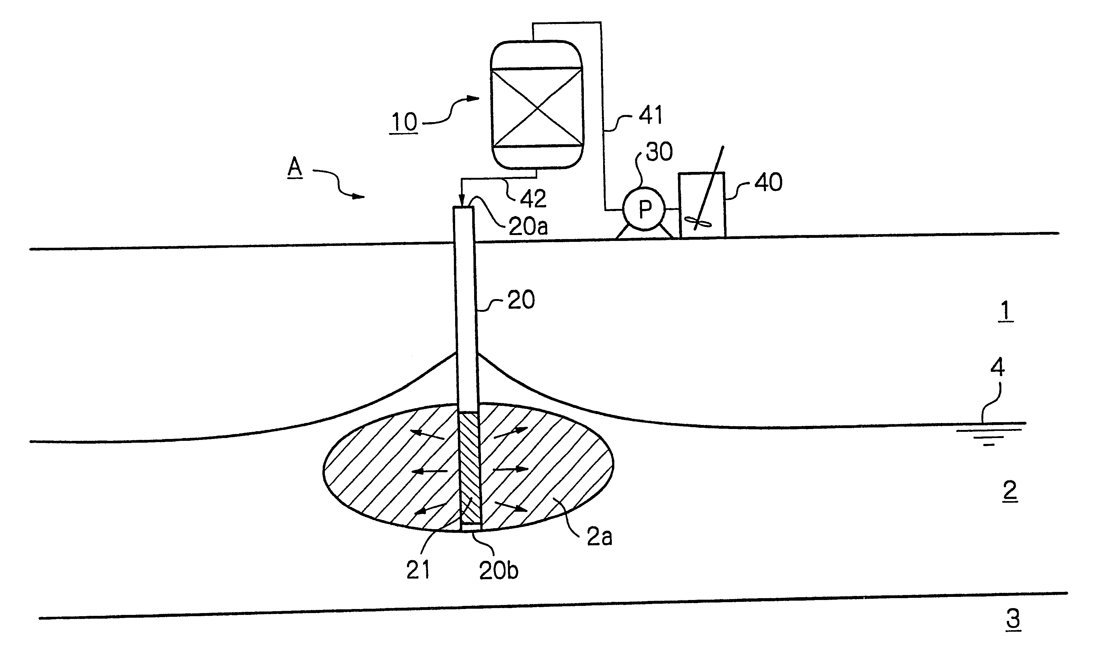
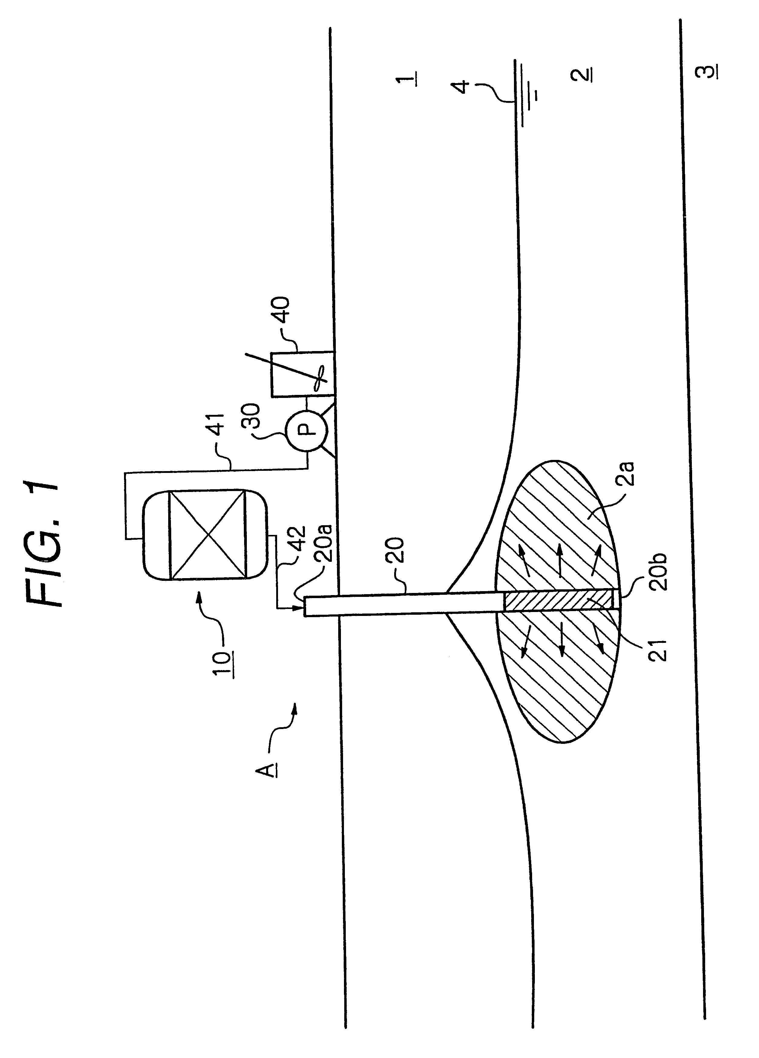
A purification apparatus B of the present embodiment is the same as in the first embodiment shown in FIG. 1, except that the reduction means is a water soluble reducing agent mixing device 100, and a water soluble reducing agent tank 150, a reducing agent supply line 151, and a pump 160 provided in the reducing agent supply line 151 are included. The same elements as in FIG. 1 are illustrated using the same numerals. The water soluble reducing agent mixing device 100 accepts a first nutrient solution supply line 141 from a nutrient solution preparation tank 140, and a reducing agent supply line 151 from the water soluble reducing agent tank 150. In the present embodiment, the water soluble reducing agent mixing device 100 is a line mixer 100. A second nutrient solution supply line 142 is connected between the water soluble reducing agent mixing device 100 and a conduit 20 installed underground. The conduit 20 has a strainer portion 21 formed in a lower part thereof.

A purification me...

third embodiment

Next, the present invention is schematically shown in FIG. 4. A purification apparatus C of the present embodiment is in the same configuration as the purification apparatus A shown in FIG. 1, except that an introduction portion 220 having a pair of inclined portions, 220c and 220d, and a strainer portion 221 inserted laterally in an aquifer 2 is provided instead of the conduit 20 of the purification apparatus A shown in FIG. 1. The first inclined portion 220c has an open end 220a located on the ground surface, and accepts a nutrient solution, which has been reduced in a solid reducing agent contact tank 210, from the open end 220a via a second nutrient solution supply line 241. The strainer portion 221 is located horizontally in the aquifer 2, and allows the reduced nutrient solution to pass into the aquifer 2. The second inclined portion 220d has a closed end 220b protruding from the ground surface. Alternatively, the water soluble reducing agent mixing device 100 shown in FIG. 3 ...


PUM

PropertyMeasurementUnit
volumeaaaaaaaaaa
volumeaaaaaaaaaa
pHaaaaaaaaaa

Abstract

A nutrient solution is reduced with a reducing agent, and introduced into a contaminated object. Alternatively, groundwater reduced with a reducing agent is introduced into the contaminated object. Groundwater is contacted with the reducing agent while being circulated between an aquifer and a housing. A nutrient source for heterotrophic anaerobic microorganism may also be introduced into the contaminated object. The contaminated object contaminated with halogenated organic compounds can be purified efficiently and easily.

Description

The present invention relates to a purification method and a purification apparatus capable of effectively purifying a contaminated object containing halogenated organic compounds. More particularly, the invention relates to a purification method and a purification apparatus capable of purifying a contaminated object containing chlorinated organic compounds, such as soil, sediment, sludge, or water, e.g., interstitial water of sludge or groundwater, by a chemical reaction or a reductive dehalogenation reaction comprising a combination of a chemical reaction and a biological reaction, to degrade the halogenated organic compounds efficiently.RELATED ARTThe entire disclosure of an international application PCT / JP / 98 / 00363, filed with the Japanese Patent Office on Jan. 29, 1998, entitled "A Method for Purifying Object Contaminated with Halogenated Organic Compounds," is cited in the present patent application.In recent years, there have been one report after another on contamination of ...

Claims


Application Information

Patent Timeline
Patent Type & Authority Patents(United States)
IPC IPC(8): B09C1/10B09C1/00C02F1/70C02F3/00
CPCB09C1/002B09C1/10C02F1/705C02F3/00C02F2101/36C02F2103/06C02F2305/06
Inventor KITAGAWA, MASAYOSHISHIMOMURA, TATSUOOYA, SHUNJI
Owner EBARA CORP
Why Eureka
Try Eureka