Apparatus and method for forming weld joints having compressive residual stress patterns

a residual stress pattern and weld joint technology, applied in non-electric welding apparatus, welding/cutting auxillary devices, auxillary welding devices, etc., can solve the problems of limited welding application for certain manufacturing processes, degrading the material properties of materials, and increasing the corrosive attack of weld zones b>6/b>, so as to improve mechanical and chemical properties, improve yield strength, and improve material properties.

Inactive Publication Date: 2005-08-09
SURFACE TECH HLDG +1
View PDF49 Cites 109 Cited by
  • Summary
  • Abstract
  • Description
  • Claims
  • Application Information

AI Technical Summary

Benefits of technology

[0020]Accordingly, the present invention provides structural assemblies having weld joints with improved material properties and surface finishes and methods and apparatus of forming the same. The manufacturing methods and apparatus of the present invention provide reduced labor costs and production times over conventional methods and provide a weld joint having improved mechanical and chemical properties, including corrosion resistance, yield strength, fatigue life, and surface finish.

Problems solved by technology

Unfortunately, several significant problems have limited the application of welding for certain manufacturing processes.
One problem generally associated with welding is that the temperature required to melt or plasticize the parent materials typically degrades the material properties of the materials.
In addition, the thermal transient created in the workpieces during friction stir welding can result in the weld zone 6 becoming more sensitive to corrosive attack.
Another common problem associated with welding is the formation of tensile residual stresses in the workpieces during the welding process.
Such tensile residual stresses are known to reduce both fatigue life and increase sensitivity to corrosion-fatigue and stress-corrosion cracking in a wide variety of materials.
Another problem associated with many fusion and solid state welding processes is the production of “flash” or excess material at the edge of the weld joint.
Fatigue crack initiation can occur out of this area due to the mechanical discontinuity at the edge or “toe” of the weld.
For example, while acceptable corrosion resistance can be achieved by a post-weld heat treatment, e.g., a solution treatment at a predetermined temperature schedule with aging at a second predetermined temperature schedule, post-weld heat treatments are not economically and technically practical except for all but the smallest and simplest of geometric shapes.
Further, local heating can result in distortion and increase tensile residual stresses elsewhere in the workpiece.
However, such coatings require a second manufacturing operation, which can increase the labor and material cost and production time of the finished assembly.
Further, such coatings provide only a superficial protective layer and do not protect surfaces of the assembly that cannot be accessed.
In addition, protection of the assembly surface is lost if the coating is broken or deteriorates during service.
However, such methods for inducing compressive stress in a prescribed pattern along a weld joint or induced along the surface of the resulting welded assembly have not been used or contemplated as a facet of the welding process, since the process for inducing a compressive stress could result in damage or weakening of the weld joint.
However, excess cold working can produce tensile surface residual stresses or spalling damage and can leave the surface susceptible to overload and thermal relaxation.
While shot peening and gravity peening may be used for inducing compressive residual stresses along the surface of the weld joint, unfortunately, shot peening and gravity peening also impart an uncontrolled amount of cold work making it difficult to optimize the material properties of the weld joint.
Further, the degree of cold working of the material by shot peening or gravity peening is relatively high, which may be undesirable for many applications.
In addition, the shot or gravity peening induced compressive residual stresses are relatively shallow, affording little benefit in arresting fatigue or stress corrosion cracks since the shallow compressive layer may be lost to wear or corrosion in service thereby providing little beneficial effects.
Shot peening and gravity peening also produce a poor surface finish making the processes unacceptable for many applications.
It is also known that the beneficial effects produced by shot peening or gravity peening are generally lost as the pattern of compression relaxes with time, particularly when subjected to elevated temperatures during service.
In addition to material property degradation and the formation of tensile residual stresses, another problem associated with assemblies formed using both solid state and fusion welding techniques is the creation of relatively rough surface finishes.
Surface roughness is generally unacceptable for structures used in fatigue loading applications.
However, decreasing the travel speed of the tool can significantly increase welding time.
However, post-weld machining can thin the weld joint and requires a relatively labor-intensive and time-consuming secondary manufacturing operation, which will increase the cost and production time of the finished assembly.
In addition, due to the differences in material hardness proximate to the weld joint that result from the soft heat affected zone, it can be difficult to prevent local undercutting when performing the post-weld machining, which can result in fatigue initiation sites.
It should now be apparent that until now, in addition to the problems identified above, all post welding procedures have required a second-pass operation that typically increases the labor and / or material cost and production time of the finished assembly.

Method used


Image

  • Apparatus and method for forming weld joints having compressive residual stress patterns
  • Apparatus and method for forming weld joints having compressive residual stress patterns
  • Apparatus and method for forming weld joints having compressive residual stress patterns

Examples


Embodiment Construction

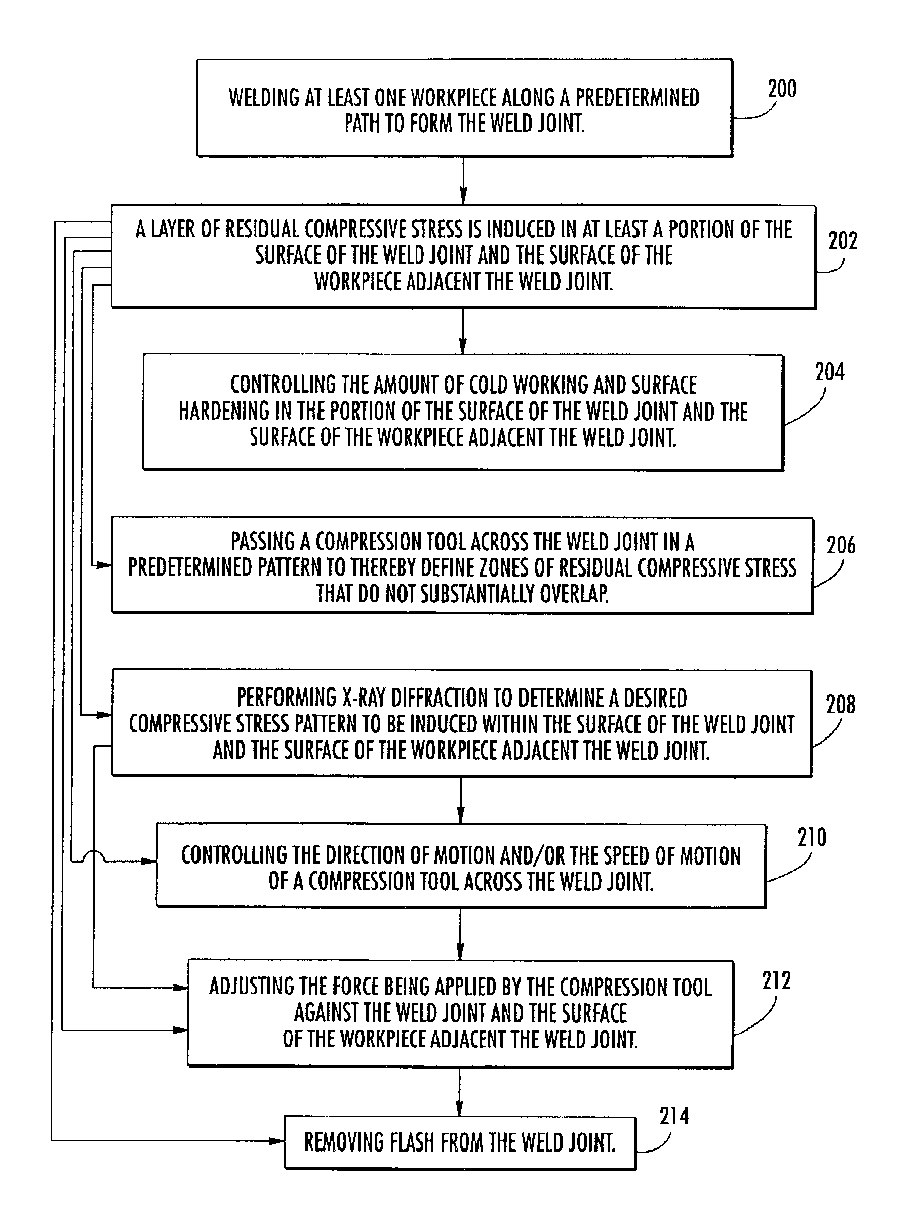
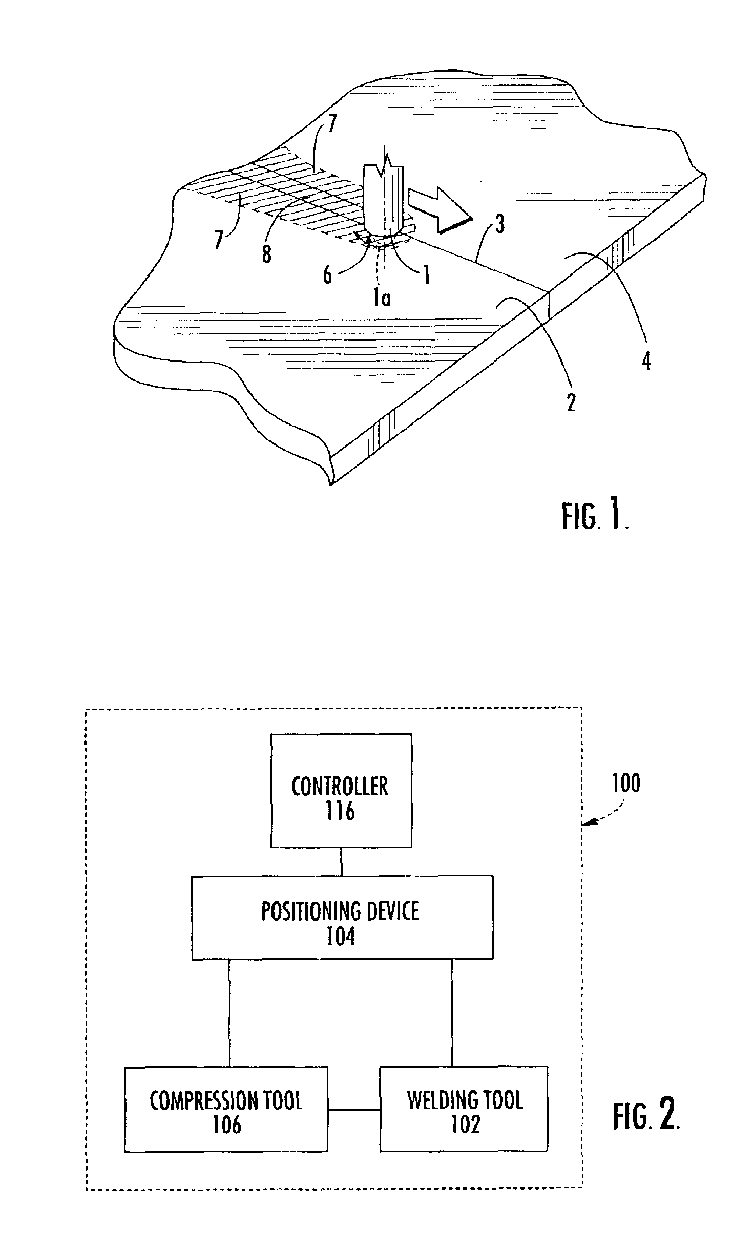
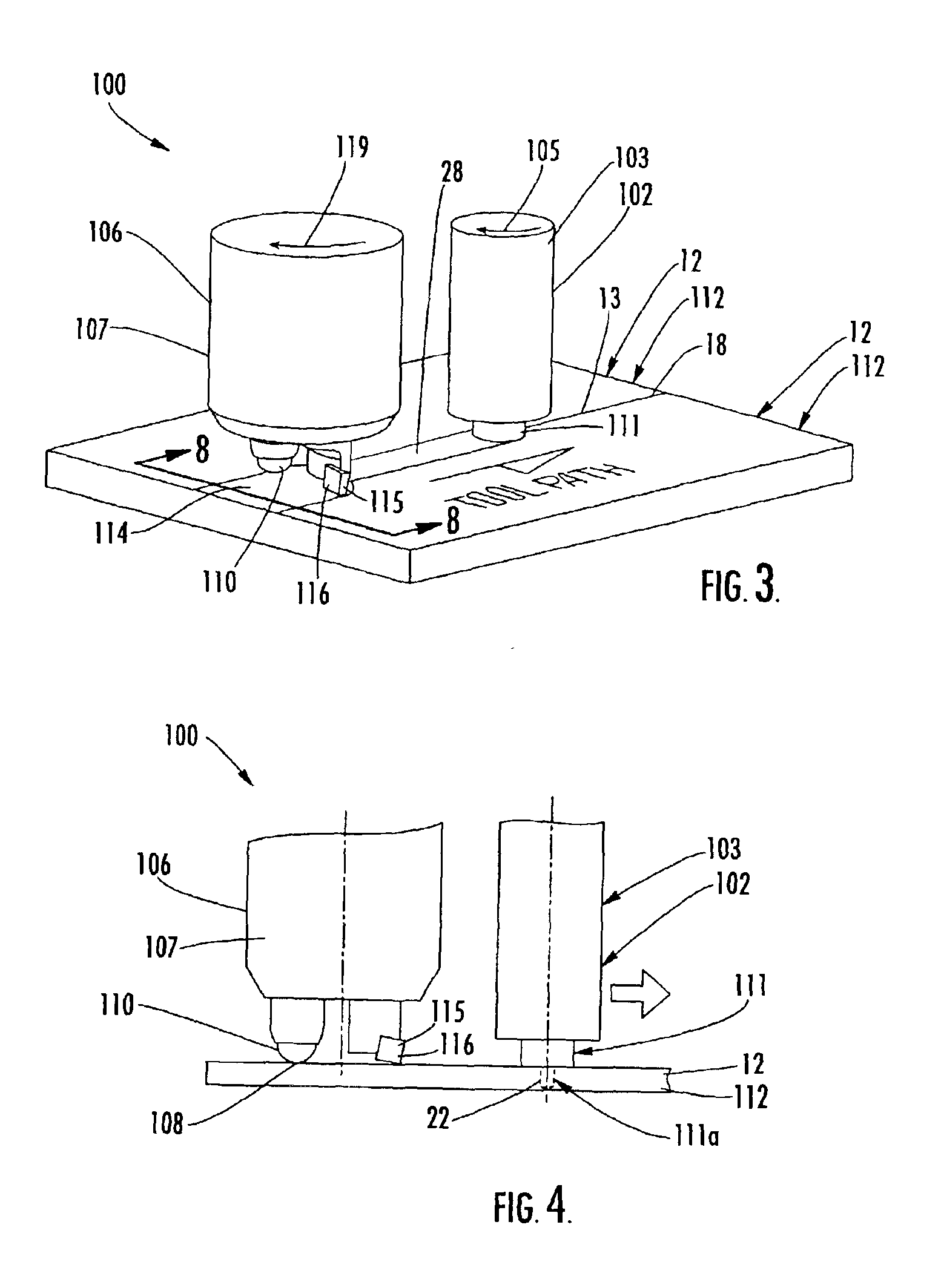
[0031]The present invention now will be described more fully hereinafter with reference to the accompanying drawings, in which some, but not all, embodiments of the invention are shown. This invention may be embodied in many different forms and should not be construed as limited to the embodiments set forth herein; rather, these embodiments are provided so that this disclosure will be thorough and complete, and will fully convey the scope of the invention to those skilled in the art. Like numbers refer to like elements throughout.

[0032]Referring to the drawings and, in particular to FIG. 8, there is illustrated a structural assembly 112, according to one embodiment of the present invention. The structural assembly 112 can be used in a variety of applications, including, but not limited to, automobiles, aerospace vehicles, construction applications, marine applications, and the like. The structural assembly 112 includes one or more workpieces 12 and at least one weld joint 28 dispose...


PUM

PropertyMeasurementUnit
depthaaaaaaaaaa
depthaaaaaaaaaa
grain sizesaaaaaaaaaa

Abstract

The welding apparatus and associated method are provided. The welding apparatus includes a welding tool for forming a weld joint along the surface of at least one workpiece. The welding apparatus also includes a compression tool for selectively inducing a layer of residual compressive stress in at least a portion of the surface of the weld joint and the surface of the at least one workpiece to thereby improve the material properties of the workpiece, including corrosion resistance and fatigue strength.

Description

CROSS REFERENCE TO RELATED APPLICATIONS[0001]This application claims the benefit of U.S. Provisional Application No. 60 / 335,739, filed Nov. 2, 2001.BACKGROUND OF THE INVENTION[0002]1. Field of the Invention[0003]This invention relates to an apparatus and a method for forming weld joints having improved material properties and, more particularly, to a method of forming weld joints that induces residual compressive stress patterns to improve the material properties of the weld joint.[0004]2. Description of Related Art[0005]In the manufacture and construction of many types of structures, welding, such as gas welding, arc welding, resistance welding, thermite welding, laser welding, and electron-beam welding, has reduced or replaced the use of various types of fastening methods, such as bolting, riveting and the like. Such welding techniques either involve the complete fusion of material proximate to the weld joint thereby forming a liquid state which subsequently solidifies producing a...

Claims


Application Information

Patent Timeline
Patent Type & Authority Patents(United States)
IPC IPC(8): B23K20/12B24B39/00B23K31/02B23K37/08C21D7/00C21D7/08B23K31/00B23K37/00
CPCB23K20/122B23K20/123B23K20/1275B23K31/02B23K37/08B24B39/00C21D7/08Y10T428/12493B23K2203/12B23K2203/14B23K2203/18B23K2203/10B23K2103/10B23K2103/12B23K2103/14B23K2103/18
Inventor JAMES, MICHAEL ROYSTONMAHONEY, MURRAY W.WALDRON, DOUGLAS J.PREVEY, III, PAUL S.
Owner SURFACE TECH HLDG
Why Eureka
Try Eureka