Quartz glass thermal sprayed parts and method for producing the same

a technology of quartz glass and thermal spraying, applied in the field of parts, can solve the problems of film deposits on not only the film substrate but also the machine parts such as bell jars, peeling away, and often occurring, and achieve the effects of improving the adhesiveness between the quartz glass film and the substrate, improving the adhesiveness of the parts to and with other parts, and good adhesiveness and sealability

Inactive Publication Date: 2006-07-25
TOSOH CORP
View PDF25 Cites 16 Cited by
  • Summary
  • Abstract
  • Description
  • Claims
  • Application Information

AI Technical Summary

Benefits of technology

[0023]As a result of extensive investigations to overcome the above-described problems, it has been found that quartz glass thermal sprayed parts fabricated by thermal spraying quartz glass on a substrate do not crack or cleave, and, in particular, when the surface roughness of the thermal sprayed quartz glass layer is at least 5 μm, the ability of the parts to hold a deposited film thereon is good, and when it is lower than 5 μm, the adhesiveness and the sealability of the parts to and with other parts is good. It has further been found that, when the density and the porous condition of the quarts glass film formed on the parts are varied, the ability of the parts to hold the deposited film thereon and the adhesiveness between the quartz glass film and the substrate is further improved, and even after the parts are washed with hydrofluoric acid, they can still have the ability to hold the deposited film thereon. It has still further been found that the parts coated with a thermal sprayed quartz glass film containing a blackening element introduced thereinto have good heat insulation property and, in addition, deterioration due to crystallization of the quartz glass does not occur.

Problems solved by technology

In forming a film of polysilicon, silicon nitride, silicon oxide or the like on a film substrate in the production of semiconductors and others, the problem often occurred that the film deposits on not only the film substrate but also the machine parts such as reactor tubes, bell jars, etc.
The deposited film on the machine parts increases its thickness through repetition of the film-forming operation, thereby the parts crack due to the difference in thermal expansion between the deposited film and the parts, or the deposited film may peel away from the parts to pollute the area inside the machine.
However, in case where the deposited film is difficult to remove through treatment with hydrofluoric acid and when the parts are readily corroded with hydrofluoric acid (e.g., quartz glass parts), the method is the problem that the parts themselves are further corroded on the area thereof in which the deposited film is partially lost through washing with hydrofluoric acid, and as a result, the parts further deteriorate.
However, the parts with a film of Mo, W, Al, WC, alumina or the like formed on a substrate still have the problem that the film itself readily peels off.
In addition, in the technical field in which quartz is used for the substrate, the coating composition for the film is unfavorable as causing impurities, and therefore it has been often reluctant to use those films.
However, the quartz glass parts processed through blasting have mircocracks on the roughened surfaces thereof, and the fragments of the parts that start from the microcracks thereof become impurities in devices.
Another problem in the parts is that their life is short since their mechanical strength is low, and impurities readily penetrate into the microcracks to devitrify the parts.
The problem of fragmentation to give impurities could not still be solved even though blasting is combined with acid etching for processing the parts.
Therefore, repeatedly washing the parts has the problem that their ability to hold the deposited film thereon lowers.
However, the parts of this type have the problem that their surfaces are liable to be smoothed through acid washing and their ability to hold the deposit thereon readily lowers.
In case where quartz glass is used for parts (e.g., core tubes) of thermal treatment devices, there is the problem that the thermal energy inside the devices may leak out to lower the thermal efficiency of the devices since quartz glass is highly transparent.
However, such still has the problem that its adhesiveness (sealability) to other parts in their bonding area is not good since the bubbles may be exposed out on the surface of opaque quartz glass to worsen the surface smoothness of the glass.
However, the porous opaque quartz glass has the problem that the sealability of the flange formed of it is not good since the bubbles may be exposed out on the surface of the glass.
Another problem is that when the parts formed of porous opaque quartz glass are washed with nitric acid / hydrofluoric acid or the like after use, their surface smoothness is greatly lowered and they soon become useless.
However, the parts thus fabricated by welding a transparent glass sheet to their flanges formed of opaque quartz glass still have the problem that they are readily cracked and, in addition, the welded part is readily cleaved.
In addition, the welding operation requires some technical skill and is therefore unsuitable to industrial use.
However, this still has the problem that the transparent quartz glass layer formed on the opaque quartz glass substrate is readily cracked and quartz glass parts having a complicated shape could not be fabricated.
Another problem is that, in the Verneuil's method, since the substrate is maintained at high temperature of 1,900° C. or higher for a long period of time, impurities may diffuse out of the substrate even when the substrate is formed of synthetic quartz glass of high purity, and the purity of the surface of the parts fabricated is thereby lowered.
However, this has also the problem that, when the mechanically-worked surfaces of the sintered quartz glass parts are locally heated, they receive stress and are thereby cracked or cleaved.
However, this method also has the problem that, when such a high-purity quartz glass film is formed on parts through plasma CVD, its thickness is at most tens μm or so, and the film is therefore not enough to flatten the rough surfaces of the parts formed of opaque quartz glass and to prevent the diffusion of impurities.
However, alumina and yttria have the problem as impurities in production of semiconductors as described hereinabove, and they are unsuitable for the thermal spraying material for parts.
In addition to the problem of sealability as described above, another problem in the oxidative diffusion treatment devices and CVD devices for use in semiconductor production is that the thermal efficiency lowers through thermal diffusion from the devices and the throughput in the devices is therefore low.
Therefore, the glass must be melted in a reducing atmosphere or in vacuum, which, however, has the problem that a particular apparatus is necessary for the specific atmosphere control.
Another problem in the conventional blackened quartz glass is that, when it is used at high temperatures, the metal element added thereto for blackening it may pollute the area inside the chamber or may crystallize to deteriorate the glass.
However, the problem of deterioration of quartz glass due to crystallization thereof could not be completely solved by that method.
In addition, the method has another problem that it requires a large-scaled vacuum furnace and the method itself is troublesome and, in addition, the size of the parts obtainable in the method is limited and the method could not apply to large-sized parts.
However, the method of using oxyhydrogen flames has the problem that the element added to the glass for blackening it is oxidized and the glass is thereby often vitrified.
In addition, the method could not still solve the problem of crystallization of quartz glass.
In addition, since the accuracy of the thickness and the width of the thickened layer could not be controlled in the method, the parts fabricated in the method must be mechanically worked in post treatment and large-sized quartz glass parts are difficult to fabricate in the method.
As described above, the parts of film-forming devices, oxidative diffusion treatment devices, plasma-treating devices and others have many problems that the deposited film thereon peels away to give particles, their ability to hold the deposited film lowers after repeatedly washed with acid, their surface smoothness is not good therefore causing bonding failure (airtight sealing failure) to other parts, and their energy efficiency is low as their heat insulation is not good.

Method used


Image

  • Quartz glass thermal sprayed parts and method for producing the same
  • Quartz glass thermal sprayed parts and method for producing the same
  • Quartz glass thermal sprayed parts and method for producing the same

Examples


example 1

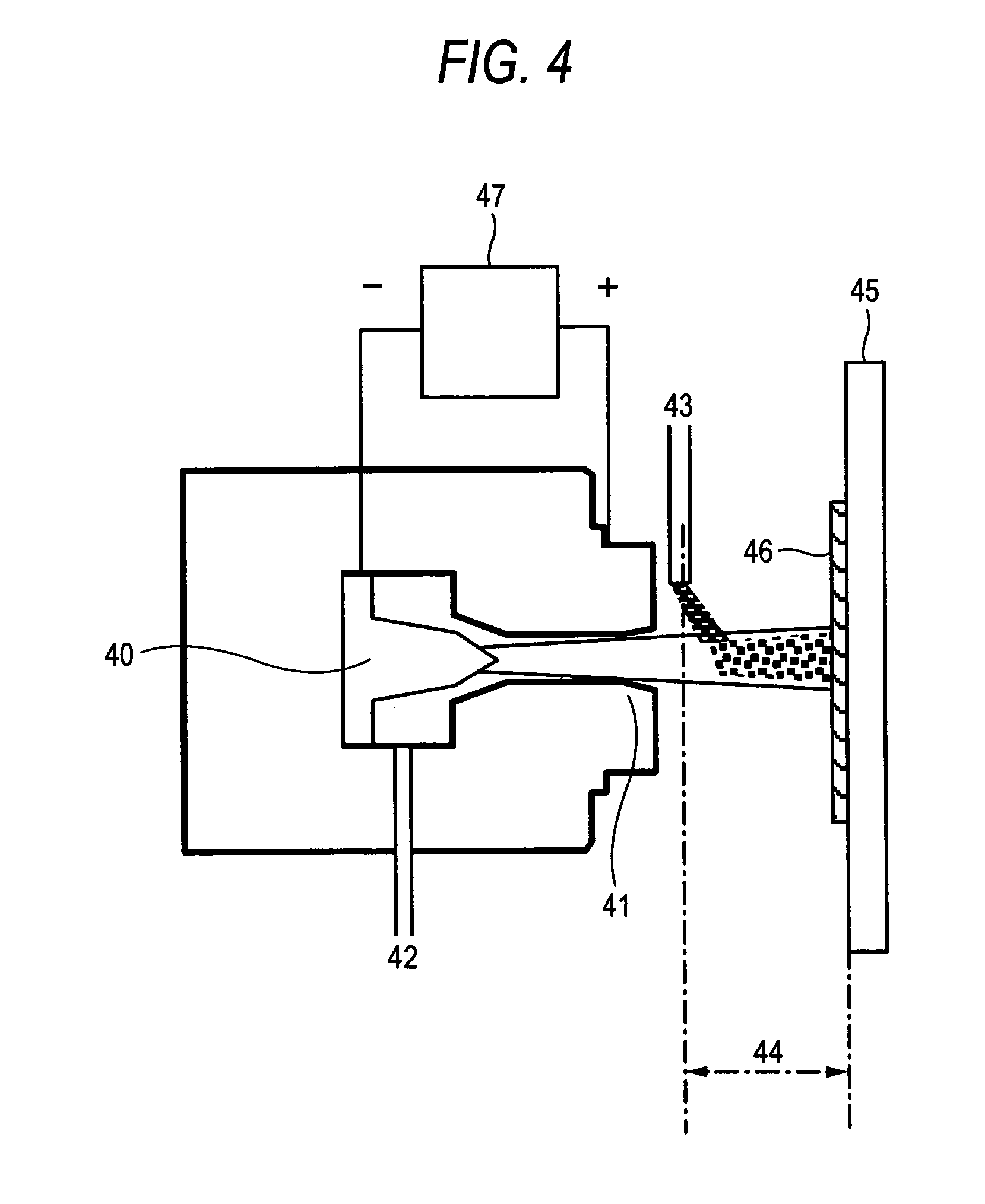
[0159]Using a plasma thermal spraying apparatus as in FIG. 4, a quartz glass film was formed on a polished quartz glass substrate. The plasma thermal spraying condition is shown in Table 1. To define the thermal spraying condition, a test sample of a blasted quartz glass substrate was tried. The condition under which the surface of the test sample melted to be transparent was employed for the thermal spraying condition in this Example.

[0160]A quartz glass thermal spraying material having a mean grain size of 15 μm, 30 μm, 50 μm or 80 μm was sprayed on the substrate to produce quartz glass thermal sprayed parts, in which the quartz glass film formed had a surface roughness Ra of 12, 23, 35 or 46 microns and a relative density of 88, 78, 70 or 65%, respectively.

[0161]FIG. 6 is a SEM image of the surface of the quartz glass thermal sprayed part produced herein.

example 2

[0163]Using a multi-torch plasma thermal spraying apparatus as in FIG. 5, the same substrate as in Example 1 was plasma thermal sprayed with quartz glass powder under the condition as in Table 1. The length of the thermal plasma was about 300 mm, and the plasma was in the form of a laminar flow. The quartz powder used herein had a mean particle size of 30 μm. The thermal spraying distance from the thermal spray gun was varied to be 90 mm, 120 mm and 140 mm. In that condition, three deposit layers (lower layer, middle layer, upper layer) were formed to be a thermal sprayed quartz glass film on the substrate.

[0164]Thus fabricated, the surface roughness Ra of the quartz glass thermal sprayed part was 35 μm; and the relative density of the quartz glass film was 80% in the upper part, 95% in the middle part and 100% in the lower part. The film had fine bubbles, but did not have any large pores of 100 μm or more. The mean inclination angle of the hillocks and recesses formed in the surfac...

example 3

[0165]Plasma thermal spraying was effected in the same manner as in Example 2, in which, however, quartz powder having a mean particle size of 100 μm was used.

[0166]Thus fabricated, the surface roughness Ra of the quartz glass thermal sprayed part was 90 μm; and the relative density of the quartz glass film was 77% in the upper part, 92% in the middle part and 100% in the lower part. The film had fine bubbles, but did not have any large pores of 100 μm or more. The mean inclination angle of the hillocks and recesses formed in the surface of the quartz glass film was 40°.


PUM

PropertyMeasurementUnit
surface roughnessaaaaaaaaaa

Abstract

Parts, especially those formed of quartz glass, for film-forming devices, plasma-treating devices and the like have a problem of inner pollution of the devices with particles given by dropping of deposit films from the parts, a problem of hermetical sealing reduction due to bonding failure of the parts to other parts, and a problem of energy efficiency reduction due to the heat insulation failure in the parts. Parts having a thermal sprayed quartz glass film formed on a substrate have an increased ability to hold a deposit thereon, and have an increased ability to hermetically bond to other parts. The parts having a thermal sprayed black quartz glass film have an increased ability of heat insulation property. Even when washed with acid, the abilities of the parts do not lower. The parts can be used for a long period of time and their life is long.

Description

FIELD OF THE INVENTION[0001]The present invention relates to parts used in production devices for semiconductors and the like, and in particular to parts that give little dust and few particles to be caused by peeling of film-like materials having been deposited thereon or by deterioration of the parts themselves by plasma, parts having good adhesiveness in the bonding area to other parts, and parts having good heat insulation and durability.[0002]The parts of the invention are produced by thermal spraying quartz glass on a substrate, and the substrate mainly comprises quartz glass, and may comprise metals or ceramics. The quartz glass thermal sprayed parts of the invention have a quartz glass thermal sprayed film excellent as a protective film or a barrier film, and hence are suitable as parts used in oxidative diffusion treatment devices, CVD film-forming devices, plasma treatment devices (plasma etching devices, plasma cleaning devices), lamp annealing devices and the like, that ...

Claims


Application Information

Patent Timeline
Patent Type & Authority Patents(United States)
IPC IPC(8): B23B3/00C23C4/10
CPCC23C4/105Y10T428/24628Y10T428/24926Y10T428/24942Y10T428/24479Y10T428/24917C23C4/11Y10T428/249953Y10T428/31678H01L21/302
Inventor TAKAHASHI, KOYATAKOHGO, MASANORI
Owner TOSOH CORP
Why Eureka
Try Eureka