
Multi-layer ceramic composite material with a thermal-protective effect

a composite material and multi-layer ceramic technology, applied in the direction of electrical equipment, anti-tornado missiles, closures, etc., can solve the problems of high temperature at the nose cone of such missiles, impaired radar equipment situated behind the nose cone, and the upper limit of the usage temperature of 650 to 760°

Inactive Publication Date: 2006-10-10
LFK LENKLUGKOERPERSYST
View PDF11 Cites 18 Cited by
  • Summary
  • Abstract
  • Description
  • Claims
  • Application Information

AI Technical Summary

Benefits of technology

[0020]Based on the known disadvantages of existing oxidic, filament-reinforced ceramics, an object of this invention is development of a composite material which provides the desired thermal protection, radar transparency, and thermal mechanical characteristics and can also be produced in a simple and cost-effective manner.
[0029]The colloidal process used for the production of the first layer results in carbon-free oxide ceramics which, because of the high purity, are distinguished by low dielectric losses as well as by high thermo-mechanical endurance in the entire usage temperature range. In addition, the colloidal process provides a simple and cost-effective production method.
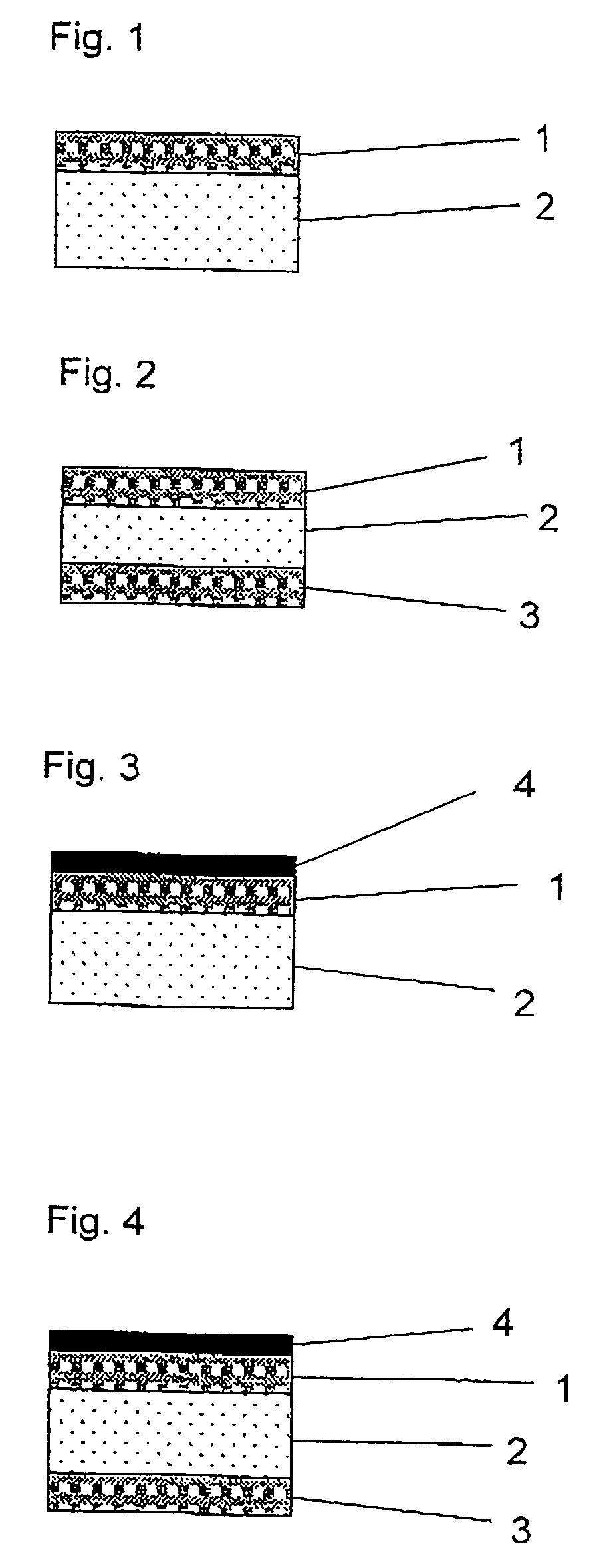
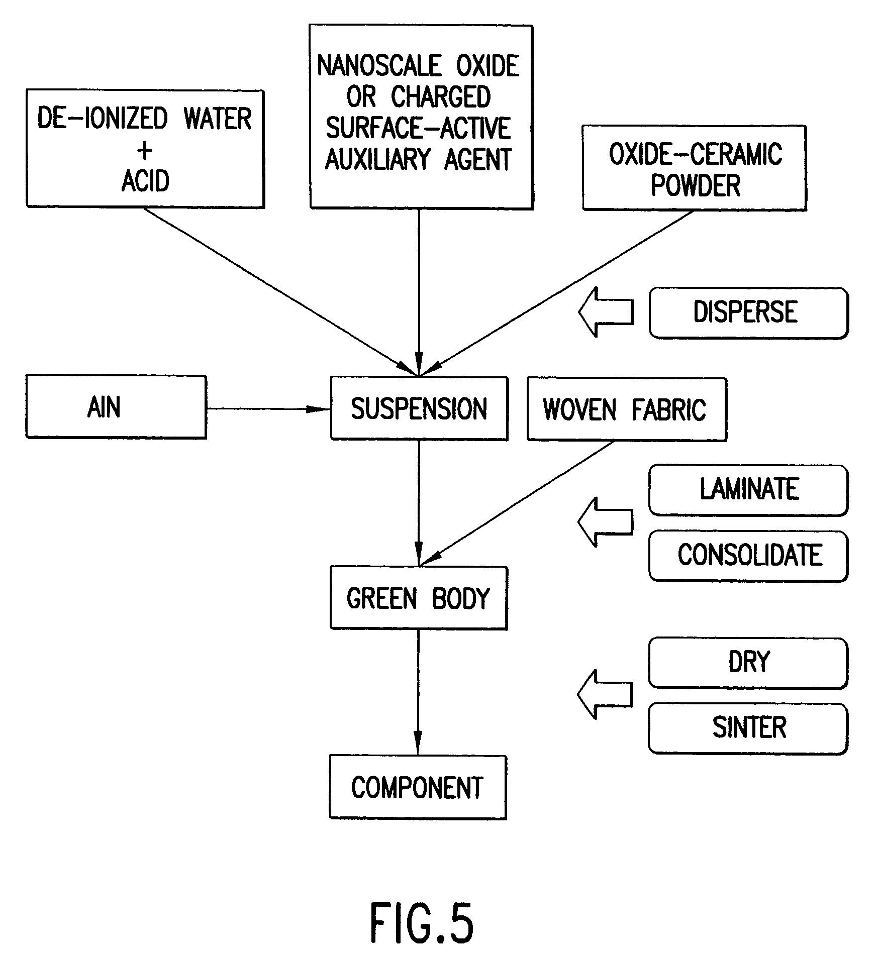
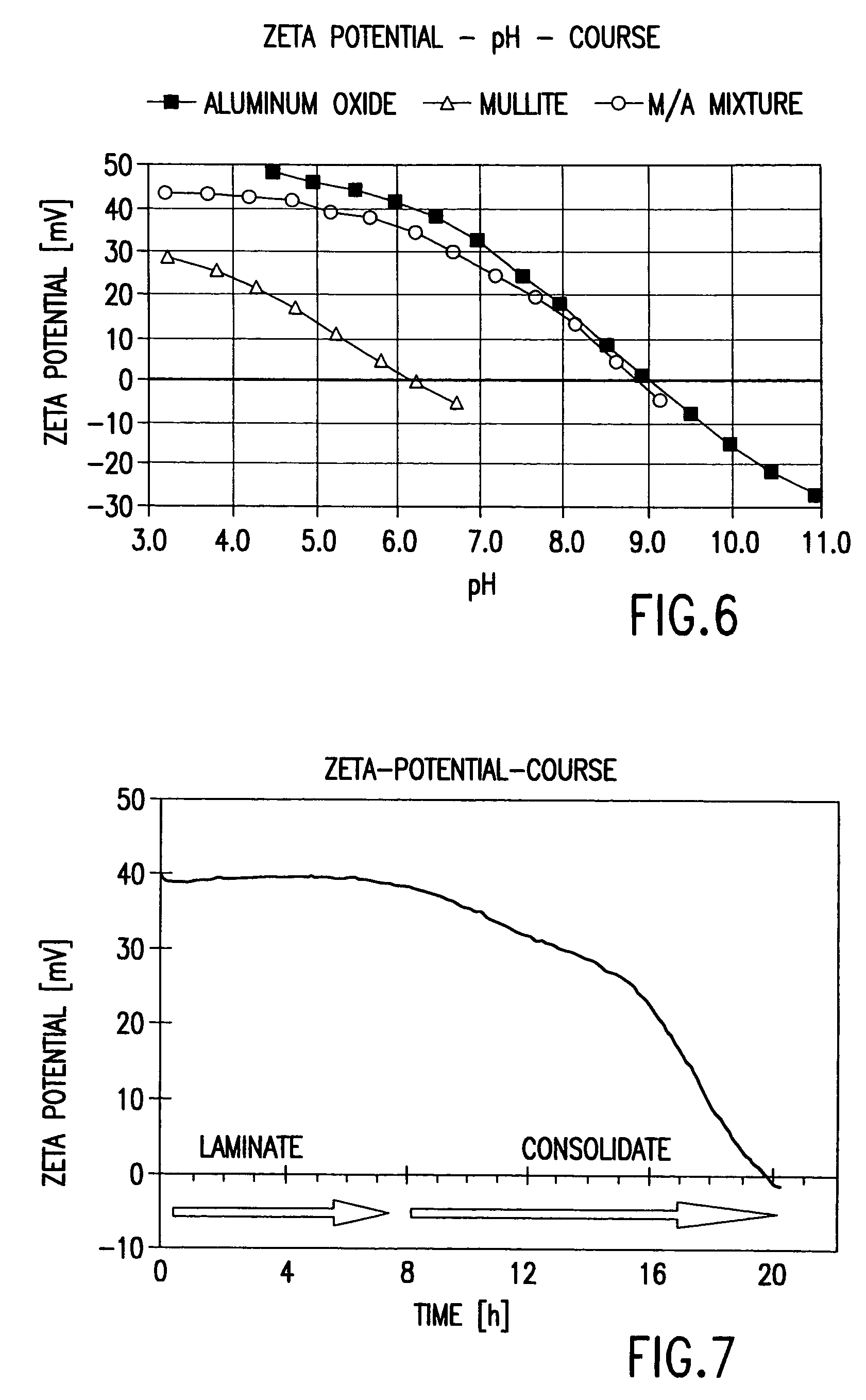
[0031]The composite material according to the invention can be produced by technically comparatively simple processes which are cost-effective in their implementation. Improvements are achieved in that aqueous suspensions of low viscosity are used for the matrix build-up of the first fiber-reinforced layer. These suspensions are ecologically acceptable and ensure a homogeneous and complete infiltration of the spaces between the fibers. The construction of laminates can take place by conventional manual laminating techniques, which have been known for a long time from the plastics industry for the production of fiber-reinforced plastics. For this purpose, non-porous metal or plastic molds as well as the vacuum bag technique for degassing and consolidation can be used. This allows for the cost-effective production of large-surface light-weight structures of a complicated geometry while the piece numbers are low, as is typical for components made of fiber-reinforced ceramics. If higher piece numbers are required, conventional automated laminating techniques may also be used. Alternatively, an infiltration of three-dimensional reinforcing architectures may be performed. Sufficiently long processing time periods (approximately 6 to 8 hours) are available for the infiltration and the laminating at room temperature. The consolidation of the composite of the matrix and the fiber takes place without organic or polymeric auxiliary agents and without the withdrawal of water at room temperature within 24 hours. The consolidation occurs via an in-situ reaction which results in reduction of the repelling particle interaction forces and forming of a low-defect texture without density gradients. Since the matrix build-up takes place without the use of inorganic polymers or precursors as well as without the use of temporary organic binders, no unbinding is required. Additionally, a matrix with a high chemical purity is formed without any carbon impurities. The subsequent drying and sintering can take place in a free-standing manner in air. Furthermore, subsequent reinfiltration cycles are not required.

Problems solved by technology

As a result of aerodynamic heating, very high temperatures occur at the nose cone of such missiles.
During the short flight, suitable thermal protection systems have to prevent heat from penetrating through the nose cone so that the functions of the radar equipment situated behind the nose cone are impaired.
The disadvantage of such radomes is that the upper limit of the usage temperature of from 650 to 760° C.
This dramatically impairs the radar-optimal characteristics and no longer meets the required transmission characteristics.
Such radomes are therefore unsuitable for future missiles.
Furthermore, the material described in U.S. Pat. No. 5,738,750 has an upper usage temperature limit in the oxygen-containing atmosphere of approximately 1,090° C. because, near that temperature, elementary carbon separates from the SiOxCy phase, which leads to a clear deterioration of the dielectric characteristics.
CVI processes have the disadvantage that they are very cost-intensive and difficult to control.
Here, the disadvantages are the difficult process control, the fiber corrosion as a result of the molten metal and the retention of residual metal as a result of incomplete oxidation.
The conversion to ceramics is connected with large volume shrinkages and resulting crack formations within the matrix.
A filling of the crack network and an increase of the matrix density normally takes place in multiple reinfiltration steps which represent considerable time and cost expenditures.
Although the C-fraction can be lowered by means of high-temperature aging under oxidative conditions, the C-fraction can be lowered, this is connected with considerable time and cost expenditures.
However, when such a material is used at high temperatures, the material has an upper time and temperature limit, as elementary carbon forms by further pyrolysis.
This is a significant disadvantage for a use as a radome material because even the smallest quantities of carbon impair the dielectric characteristics.
The consolidation takes place by hot-pressing or high-temperature isostatic pressing, which conventionally require considerable system-related expenditures and are limited to components having a simple geometry.
However, the drying and sintering of gels is connected with very large volume shrinkages, which leads to high porosity of the matrix and to crack formation.
Filling in the cracks and reducing the porosity requires multiple reinfiltrations and sintering cycles which are connected with considerable time and cost expenditures.
Although chemically pure oxides can be produced, the high drying shrinkage frequently leads to crack formation.
The production of laminates and a further densification of the matrix takes place in an additional process step by means of filter pressing, which may result in density gradients in the laminates and thus limits the production of complicated component geometries.
However, this process requires multiple reinfiltration cycles, which result in considerable time and cost expenditures.
Additionally, the process technique of filter pressing, which lead to density gradients in the laminate and limits the production of complicated component geometries.
Disadvantages of this process are caused by the winding technique and the high matrix porosity.
Because of the winding technique, these characteristics cannot be improved by using three-dimensional reinforcing architectures.
Another disadvantage is the use of a temporary binder and of organic auxiliary agents which require an additional process step for the thermal unbinding.
These processes have no significance for the production of filament-reinforced ceramics because they do not meet the requirements with respect to a fiber-preserving complete and homogeneous infiltration of the spaces between the fibers by means of matrix, and also do not permit an economical production of large-surface, light-weight structures having a complicated geometry.
This consolidation mechanism by the withdrawal of water has the important disadvantage that a migration of fine particles and soluble constituents will occur which leads to inhomogeneous textures with density gradients.
The plaster molds also have to be dried after each use, which represents additional expenditures.
The process has the disadvantage of using enzymes which are expensive and often require special storage.
They may be inhibited in their effectiveness by interactions with constituents of the slip, which makes the development of the suspension more difficult.
With respect to possible use for producing filament-reinforced ceramics, the very high solids contents of the suspensions are problematic because, as a result of the connected high viscosities, a homogeneous and complete infiltration of the space between the fibers cannot be achieved.
The relatively short consolidation times in the range of between 30 minutes and 2 hours have the result that the viscosity of the suspensions rises considerably after as little as a few minutes, which is much too short as a processing period for conventional infiltrating and laminating techniques.
The consolidation takes place by heating the suspension above the hydrolysis temperature of the metal nitride which, when aluminum nitride is used, is at temperatures between 50° C. and 70° C. By means of the hydrolysis, the suspending agent is partially withdrawn from the suspension and, in certain cases, the pH-value is shifted, which leads to a steep increase of the viscosity.
One disadvantage of the process is the necessary heating of the suspension and the connected use of heated molds.
Because of the high contents of solids, the same problems occur with respect to possible use in the production of filament-reinforced ceramics, since the resulting high viscosities make a homogeneous and complete infiltration of the spaces between the fibers more difficult.
Furthermore, the consolidation times are still shorter than in the previously mentioned process, which is much too short as a processing time period for customary infiltrating and laminating techniques.

Method used


Image

  • Multi-layer ceramic composite material with a thermal-protective effect
  • Multi-layer ceramic composite material with a thermal-protective effect
  • Multi-layer ceramic composite material with a thermal-protective effect

Examples


example 1

[0050]An acidic suspension was produced in that a corresponding quantity of mullite powder and aluminum oxide powder was dispersed in de-ionized water. With the pH-value of the suspension adjusted to a value lower than pH 5 by the addition of a 5 molar HNO3 solution. The suspension was deagglomerated by means of ultrasound. A little aluminum nitride powder was added to the suspension and homogeneously dispersed by means of an ultrasonic treatment. Subsequently, the low-viscosity suspension was degassed by means of a rotary evaporator in order to remove possibly trapped air. Eight oxidic woven-fabric layers with the desired dimensions were infiltrated with a suspension by means of the wet-in-wet manual laminating technique and were placed in layers to form a laminate. The laminate was airtightly closed off in a vacuum bag between metal molds and was degassed for an hour. Subsequently, during the consolidation in the closed mold, the laminate was pressed together at a pressure of betw...

example 2

[0051]For producing an aqueous sample, a cationic polyelectrolyte was dissolved in a corresponding quantity of de-ionized water. An acidic suspension was produced in that mullite, aluminum hydroxide and silica powder were dispersed in the aqueous sample, with the pH-value of the suspension adjusted to a value lower than pH 5 by the addition of a 5 molar HNO3 solution. The suspension was deagglomerated by means of a ball-type mill. A little aluminum nitride powder was added to the suspension and homogeneously dispersed by means of an ultrasonic treatment. Subsequently, the low-viscosity suspension was degassed by means of a rotary evaporator in order to remove possibly trapped air. Eight oxidic woven-fabric layers with the desired dimensions were infiltrated with a suspension by means of the wet-in-wet manual laminating technique and were placed in layers to form a laminate. The laminate was airtightly closed off in a vacuum bag between metal molds and was degassed for an hour. Subse...


PUM

PropertyMeasurementUnit
Temperatureaaaaaaaaaa
Pressureaaaaaaaaaa
Pressureaaaaaaaaaa

Abstract

A two-layer ceramic composite material, wherein the first predominantly load-bearing layer is an oxidic, carbon-free fiber-reinforced ceramic layer which is made by a colloidal process. The second predominantly thermally insulating layer is an oxide-ceramic foam. The colloidal process produces carbon-free oxide ceramics which, because of their high purity, have low dielectric losses in the entire usage temperature range. In addition, the colloidal process provides a simple and cost-effective production method.

Description

[0001]This application claims the priority of German Patent Document No. 103 18 514.3, filed 24 Apr. 2003 the disclosure of which is expressly incorporated by reference herein.FIELD OF THE INVENTION[0002]The invention relates to a multi-layer ceramic composite material with a thermal protective effect. Such composite materials are particularly suitable for thermal protection of spacecraft or missiles which heat up as a result of aerodynamic heating, the composite material taking over load-bearing, structural tasks as well as simultaneously serving as a dielectric window (radome).BACKGROUND OF THE INVENTION[0003]During the ascent and when entering the atmosphere of celestial bodies, that is, during re-entry into the earth atmosphere as well as during entry into the atmosphere of planets and moons, spacecraft are subjected to extreme aerodynamic, aerothermal, mechanical and acoustic stresses. During this very important flight phase, spacecraft have to be provided with an effective the...

Claims


Application Information

Patent Timeline
IPC IPC(8): B32B17/00B32B18/00B64C1/38B64C1/40B64G1/58C04B35/185C04B35/80H01Q1/42
CPCB32B18/00B64C1/38B64C1/40B64G1/58C04B35/185C04B35/6263C04B35/803H01Q1/424Y10T428/252C04B2235/3217C04B2235/3218C04B2235/3418C04B2235/3463C04B2235/386C04B2235/522C04B2235/5224C04B2235/5228C04B2235/5445C04B2235/721C04B2235/96C04B2235/9607C04B2237/341C04B2237/343C04B2237/38Y10T428/1376B32B2315/02C04B35/80Y10T428/249928Y10T428/249953Y10T428/3154
Inventor SIMON, REINHARD A.KNABE, HELMUT E. A.SCHAFER, WOLFGANGVOGEL, WALTER D.WULBRAND, WILHELMHAGER, WILHELMLINDNER, KURTHENNIG, PAUL
Owner LFK LENKLUGKOERPERSYST
Learn More