

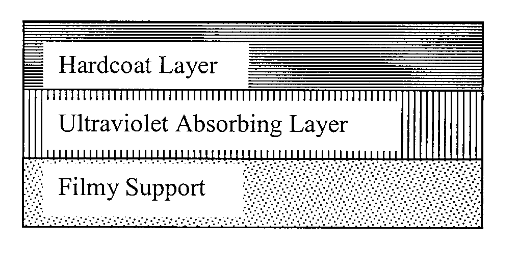
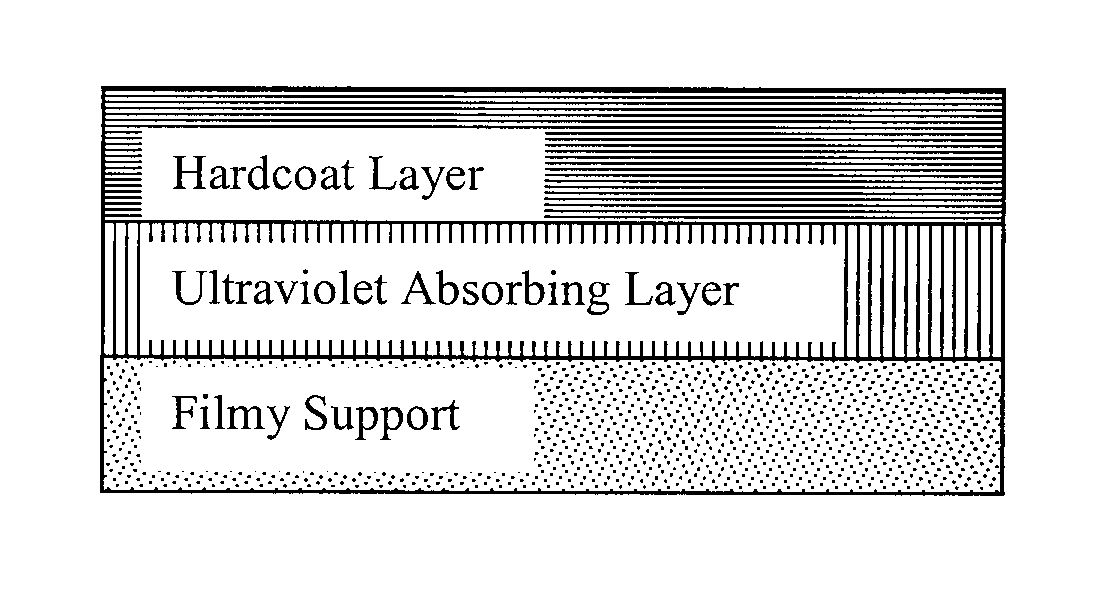
Optical film, and polarizing plate and liquid crystal display device using the optical film
a technology of optical film and polarizing plate, which is applied in the direction of polarizing elements, lighting and heating apparatus, instruments, etc., can solve the problems of disadvantageous separation of hardcoat layer and film, and achieve good antireflection ability, reduce deterioration, and prevent dimensional change
- Summary
- Abstract
- Description
- Claims
- Application Information
AI Technical Summary
Benefits of technology
Problems solved by technology
Method used
Image

Examples
synthesis example 1
Synthesis of Perfluoroolefin Copolymer (1)
[0327]In a stainless steel-made autoclave having an inner volume of 100 ml and equipped with a stirrer, 40 ml of ethyl acetate, 14.7 g of hydroxyethyl vinyl ether and 0.55 g of dilauroyl peroxide are charged, and the inside of the system is degassed and displaced with nitrogen gas. Furthermore, 25 g of hexafluoropropylene (HFP) is introduced into the autoclave, and the temperature is elevated to 65° C. The pressure when the temperature in the autoclave reaches 65° C. is 0.53 MPa. The reaction is continued for 8 hours while keeping this temperature and when the pressure reaches 0.31 MPa, the heating is stopped and the system is allowed to cool. At the time when the inner temperature drops to room temperature, the unreacted monomer is expelled and the autoclave is opened to take out the reaction solution. The obtained reaction solution is poured in a large excess of hexane and after removing the solvent by decantation, the precipitated polymer...
synthesis example 2
Synthesis of Ultraviolet-Absorbing Polymer Particle (J)
[0330]600 Parts of water is filled in a reaction vessel equipped with a stirrer and a reflux condenser, and 0.7 parts of polyvinyl alcohol and 2.7 parts of sodium dodecylbenzenesulfonate are added thereto and dissolved. Subsequently, a mixed solution containing 60.0 parts of an ultraviolet absorbing monomer 2-[2′-hydroxy-5′-(methacryloyloxy)ethylphenyl]-2H-benzotriazole {“RUVA-93”, trade name, produced by Otsuka Chemical Co., Ltd.}, 39.0 parts of methyl methacrylate, 1.0 part of ethylene glycol dimethacrylate and 2.0 parts of benzoyl peroxide is added thereto and stirred. This mixed solution is dispersed using a homogenizer at 9,000 rpm for 15 minutes and made uniform. The stirring is continued at 75° C. for 4 hours while blowing nitrogen gas. Thereafter, the product is lightly dehydrated by centrifugal separation, then washed with water and dried to produce Polymer Particle (J).
[Preparation of Coating Solution for Ultraviolet A...
formulation example 1-1
Preparation of Coating Solution (UV-A) for Ultraviolet Absorbing Layer
[0331]5.2 parts of sodium polyacrylate {“Poiz-530” (trade name), produced by Kao Corp.} as a dispersant, 10.5 parts of glycerin as an aggregation inhibitor and 49.3 parts of water are mixed with 5 parts of spindle-shaped fine particulate titanium oxide (TI-A) {average primary particle diameter of short axis diameter: 8 nm (short axis diameter at both ends of particle: 5 nm) and long axis diameter: 32 nm, aspect ratio: 4, rutile crystallinity: 55%}, and the mrxture is dispersed in “Dissolver” {manufactured by Tokushu Kika Kogyo Co., Ltd.} at 3,000 rpm for 30 minutes and then passed 5 times through a horizontal sand grinder at 2,500 rpm to obtain Dispersion (UV1).
[0332]Gelatin is mixed with Dispersion (UV1) such that the ratio of spindle-shaped fine particulate titanium oxide (TI-A) / gelatin in the coating solution (UV1) becomes 2 / 1. In this way, Coating Solution (UV-A) for Ultraviolet Absorbing Layer is prepared.
PUM
| Property | Measurement | Unit |
|---|---|---|
| wavelength | aaaaa | aaaaa |
| beam transmittance | aaaaa | aaaaa |
| haze | aaaaa | aaaaa |
Abstract
Description
Claims
Application Information