Impregnated continuous graphitic fiber tows and composites containing same

a graphite fiber and impregnated technology, applied in the direction of non-conductive materials with dispersed conductive materials, thin material processing, textiles and paper, etc., can solve the problems of inability to produce this type of large grain size unitary graphene entity (fiber) from existing natural or synthetic graphite particles, difficult process, and high cost, so as to reduce the viscosity of the go gel, effective shear stress, and strong shearing

Active Publication Date: 2016-06-07
GLOBAL GRAPHENE GRP INC
View PDF8 Cites 3 Cited by
  • Summary
  • Abstract
  • Description
  • Claims
  • Application Information

AI Technical Summary

Benefits of technology

[0052]The procedure of mechanical stress-induced molecular alignment can involve a shear stress. Shear-induced thinning in step (b) means the GO gel is subjected to a shear stress during processing and a viscosity of the GO gel is reduced during and / or after the application of such a shear stress. As an example, the shear stress can be encountered in a situation where the GO gel is being extruded from an extrusion die slit that has a larger inner diameter (at a distance from the exit) gradually tapered to a smaller inner diameter at the exit point. As another example, an effective shear stress is created when a stream of GO gel is dispensed from a nozzle to a moving solid substrate, such as a plastic film, where the gap between the nozzle and the moving substrate can be reduced to induce a stronger shearing effect. In contrast, conventional spinning-coagulation processes allow the extruded strands of polymer chains to relax out when brought in contact with the coagulation liquid.
[0053]In another embodiment, step (d) includes heat treating the continuous graphene oxide fiber under a stress field that includes a local tension stress along a fiber axis direction. This tension force exerted on the GO fiber helps to maintain or even enhance the molecular orientation of the fiber during a heat treatment.
[0056]The mechanical stress-induced molecular alignment (e.g. via shear-induced thinning) is a critically important step in the production of the presently invented unitary graphene-based graphitic fibers due to the surprising observation that shear-induced thinning during GO gel dispensing and deposition onto a solid substrate (as opposed to a liquid coagulation bath) enables the GO molecules to align themselves along a particular direction (e.g. the fiber-axis direction) to achieve a preferred orientation. Further surprisingly, this preferred orientation of graphene molecules is preserved and often further enhanced during the subsequent heat treatment to produce the unitary graphene-based graphitic fiber. Most surprisingly, such a preferred orientation is essential to the eventual attainment of exceptionally high thermal conductivity, high electrical conductivity, high tensile strength, and high Young's modulus of the resulting unitary graphene fiber along the fiber axis direction. These great properties in this desired direction could not be obtained without such a mechanical stress-induced orientation control.
[0066]Regime 3: 1,250° C.-2,000° C. (the ordering and re-graphitization regime); Oxygen content reduced to typically 0.01%, resulting in a reduction of inter-graphene spacing to approximately 0.337 nm (degree of graphitization from 1% to approximately 80%) and improved degree of ordering, an increase in axial thermal conductivity of the filament to >1,600 W / mK, and / or in-plane electrical conductivity to 5,000-7,000 S / cm.
[0079](5) The mechanical stress-induced graphene molecular orientation control, coupled with the nearly perfect graphene planes derived from the well-aligned graphene molecules, enable us to achieve both high strength and high Young's modulus with the presently invented continuous graphitic fibers. This has not been possible with conventional continuous carbon or graphite fibers. For instance, ultra-high strength could only be obtained with PAN-based carbon / graphite fibers, and ultra-high modulus could only be obtained with pitch-based carbon / graphite fibers.

Problems solved by technology

Regardless the type of carbon fibers or graphite fibers desired, the production of continuous carbon fibers and graphite fibers from pitch, PAN, and rayon is a tedious, energy-intensive, very challenging (requiring extreme temperature and atmosphere control), and expensive process.
Thus far, it has not been possible to produce this type of large grain-size unitary graphene entity (fiber) from existing natural or synthetic graphite particles.
In general, a paper-like structure or mat made from platelets / sheets of graphene, GO, or RGO (e.g. those paper sheets prepared by vacuum-assisted filtration process) exhibit many defects, wrinkled or folded graphene sheets, interruptions or gaps between platelets, and non-parallel platelets (e.g. SEM image in FIG. 3(b)), leading to relatively poor thermal conductivity, low electric conductivity, and low structural strength.
Clearly, this is a very tedious and time-consuming process.
Another severe problem of this process is the notion that the spinning-coagulation procedure inherently results in highly porous and non-oriented graphene sheets in the graphene fiber (e.g. FIGS. 2(c) and 2(d)).
Furthermore, this process is not a scalable process and cannot be used to mass-produce continuous graphene fibers.
These pores and helices severely weaken these conventional fibers, leading to dramatically lower elastic modulus and strength that what graphene could achieve.
When used as a reinforcement phase, these weakened fibers also result in composites of poor mechanical properties.
The limited packing factor of the fibers in a tow leads to a low fiber volume fraction in a matrix (maximum fiber volume fraction being 55%-65% in a resin matrix composite) and, hence, relatively low elastic modulus and low strength of the resulting composite.(b) These conventional continuous carbon / graphite fibers, having a typical diameter of 6-12 μm, lead to a typically thick tow and ultimately a thick fabric layer.
The material structure, size, and shape of the fibers and resulting tows may become limiting factors for the range of application of a certain fabric composite.(d) A typical CF or GF fabric is made of CF or GF yarns and, in each yarn, constituent fibers cohere to form a nearly round cross section.
Hence, in the fabric with considerably crimped yarns, the fiber density tends to be non-uniform, preventing high strength of the CF or GF from being fully exploited.
This adversely affects the resin infiltration property when manufacturing a pre-impregnated material (hereinafter referred to simply as “prepreg”), or molding a fiber reinforced resin composite.
Therefore, carbon fiber reinforced plastics (CFRP) produced by using a carbon fiber fabric woven with yarns of a large size inevitably leads to more voids present in the resin, preventing the realization of a high-strength composite.(e) Conventional continuous carbon / graphite fibers typically have a hard carbon skin layer that is difficult to functionalize and, hence, it is difficult to achieve a strong interfacial bonding between the carbon / graphite fiber and the matrix resin.
It normally requires the use of an undesirable surface treatment procedure (e.g. acid etching and plasma exposure) to improve the interfacial bonding and, in most situations, the surface treatment does not lead to a satisfactory result.
This has been a long-standing problem associated with carbon / graphite fiber-resin composites.(f) Generally, there are no available continuous fibers having a sub-micron or nanometer diameter / thickness and shape that provide significant strength, ductility, geometric flexibility, and cross-sectional shape of a yarn or tow so as to define a multi-functional fabric reinforced with a matrix material.
No prior art continuous graphitic fiber meets this set of stringent technical requirements.
These pores and helices severely weaken these conventional fibers, exhibiting dramatically lower elastic modulus and strength.
These features are not achievable with conventional graphitic fibers.

Method used


Image

  • Impregnated continuous graphitic fiber tows and composites containing same
  • Impregnated continuous graphitic fiber tows and composites containing same
  • Impregnated continuous graphitic fiber tows and composites containing same

Examples


example 1

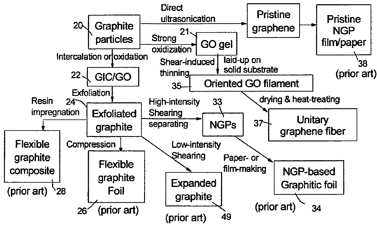
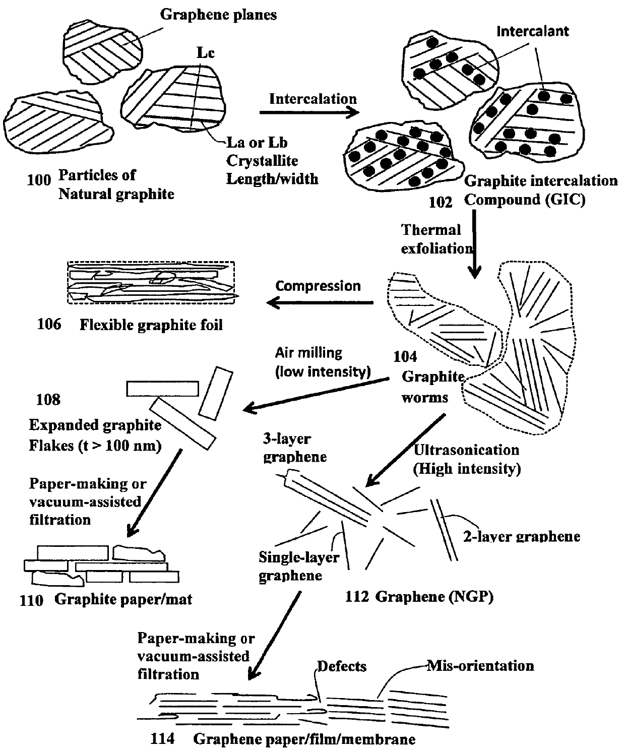
Preparation of Discrete Nano Graphene Platelets (NGPs)

[0169]Chopped graphite fibers with an average diameter of 12 μm and natural graphite particles were separately used as a starting material, which was immersed in a mixture of concentrated sulfuric acid, nitric acid, and potassium permanganate (as the chemical intercalate and oxidizer) to prepare graphite intercalation compounds (GICs). The starting material was first dried in a vacuum oven for 24 h at 80° C. Then, a mixture of concentrated sulfuric acid, fuming nitric acid, and potassium permanganate (at a weight ratio of 4:1:0.05) was slowly added, under appropriate cooling and stirring, to a three-neck flask containing fiber segments. After 16 hours of reaction, the acid-treated graphite fibers or natural graphite particles were filtered and washed thoroughly with deionized water until the pH level of the solution reached 6. After being dried at 100° C. overnight, the resulting graphite intercalation compound (GIC) was subjecte...

example 2

Preparation of Graphene Oxide (GO) Gel

[0171]In one example, graphite oxide gel was prepared by oxidation of graphite particles with an oxidizer liquid consisting of sulfuric acid, sodium nitrate, and potassium permanganate at a ratio of 4:1:0.05 at 30° C. When natural graphite (particle sizes of 14 μm) were immersed and dispersed in the oxidizer mixture liquid, the suspension or slurry appeared optically opaque and dark. The suspension remained opaque during the first 52 hours of reaction. However, the suspension gradually turned optically translucent (a little cloudy) when the reaction time exceeds 52 hours, and the color of the suspension changed from black to dark brown. After 96 hours, the suspension suddenly became an optically translucent solution with light brown color. The suspension was a solution, which appeared very uniform in color and transparency, indicating the absence of any dispersed discrete objects. The whole solution behaves like a gel, very similar to a typical ...

examples 3

Electrical and Thermal Conductivity Measurements of Various Graphene Oxide-derived Unitary Graphene Fibers

[0183]Four-point probe tests were conducted on unitary graphene fibers and coagulation-derived graphene fibers. Their in-plane thermal conductivity was measured using a laser flash method (Netzsch Thermal Diffusivity Device).

[0184]FIG. 5 (a) and FIG. 5(b) show the thermal conductivity and electrical conductivity values, respectively, of the GO gel-derived unitary graphene-based continuous fibers and those of the fibers produced by spinning of GO suspension into a coagulation bath, all plotted as a function of the final heat treatment temperature. These data have clearly demonstrated the superiority of the unitary graphene-based fibers in terms of the achievable thermal conductivity and electrical conductivity at a given heat treatment temperature. All the prior art work on the preparation of continuous graphene fibers results in a simple aggregate or twisted stack of discrete gr...


PUM

PropertyMeasurementUnit
thicknessaaaaaaaaaa
thicknessaaaaaaaaaa
volume fractionaaaaaaaaaa

Abstract

An impregnated fiber tow comprising multiple unitary graphene-based continuous graphitic fibers impregnated with a matrix material, wherein at least one of the continuous graphitic fibers comprises at least 90% by weight of graphene planes that are chemically bonded with one another having an inter-planar spacing d002 from 0.3354 nm to 0.4 nm as determined by X-ray diffraction and an oxygen content less than 5% by weight, wherein the graphene planes are parallel to one another and parallel to a fiber axis direction and the graphitic fiber contains no core-shell structure, has no helically arranged graphene domains or domain boundary, and has a porosity level less than 5% by volume.

Description

FIELD OF THE INVENTION[0001]The present invention relates generally to the field of graphite fiber-reinforced composites and, more particularly, to a new class of impregnated fiber tows and composites containing continuous graphitic fibers produced from living graphene molecules or chains. These nearly perfect graphitic fibers exhibit a combination of exceptionally high tensile strength, elastic modulus, thermal conductivity, electrical conductivity, and ease of functionalization unmatched by any type of continuous fibers.BACKGROUND OF THE INVENTION[0002]Continuous carbon fibers and graphite fibers are produced from pitch, polyacrylonitrile (PAN), and rayon. Most carbon fibers (about 90%) are made from PAN fibers and only a small amount (about 10%) is manufactured from petroleum pitch or rayon. Although the production of carbon fibers from different precursors requires different processing conditions, the essential features are similar. Generally, carbon fibers are manufactured by a...

Claims


Application Information

Patent Timeline
Patent Type & Authority Patents(United States)
IPC IPC(8): B32B5/12H01B1/24D01F9/12D01D5/04
CPCH01B1/24D01D5/04D01F9/12Y10T428/24124Y10T428/249921Y10T428/2918
Inventor ZHAMU, ARUNAJANG, BOR Z
Owner GLOBAL GRAPHENE GRP INC
Why Eureka
Try Eureka