
Electromagnetic interference resistant Mn-Zn ferrite magnet material and preparation method thereof

An anti-electromagnetic interference, zinc ferrite technology, applied to the magnetic direction of inorganic materials, can solve problems such as poor DC superposition characteristics, harmonic distortion affecting signal transmission speed, device working environment restrictions, etc., to reduce the magnetic crystal anisotropy Anisotropy constant and hysteresis loss, good anti-electromagnetic and anti-interference performance, and the effect of accelerating the grain growth rate

Inactive Publication Date: 2010-02-17
SUZHOU GUANDA MAGNET
View PDF0 Cites 4 Cited by
  • Summary
  • Abstract
  • Description
  • Claims
  • Application Information

AI Technical Summary

Problems solved by technology

[0007] Since the initial permeability (μi) of the above-mentioned MnZn ferrite is below 2700, the materials and devices will affect the signal transmission speed and generate harmonic distortion in the field of digital communication network and multimedia communication. Increasing the number of winding turns increases the distributed capacitance, thereby increasing the loss
The saturation magnetic flux density (Bs) is below 380 except for the NS10 brand of TDK in Japan, which is 480. As is known in the industry, a low saturation magnetic flux density will cause the device to easily saturate in normal working conditions and have poor performance. DC Superposition Characteristics
Low Curie temperature (Tc), the operating environment of the device is limited, and it usually cannot work in the case of attenuating electromagnetic interference signal (EMI)
It can be seen from the above table that the physical index of NS10 type MnZn ferrite of TDK Japan is better than that of the other three companies, but the initial magnetic permeability and saturation magnetic flux density are still low, and the specific temperature coefficient is high

Method used


Image

  • Electromagnetic interference resistant Mn-Zn ferrite magnet material and preparation method thereof
  • Electromagnetic interference resistant Mn-Zn ferrite magnet material and preparation method thereof
  • Electromagnetic interference resistant Mn-Zn ferrite magnet material and preparation method thereof

Examples


Embodiment 1

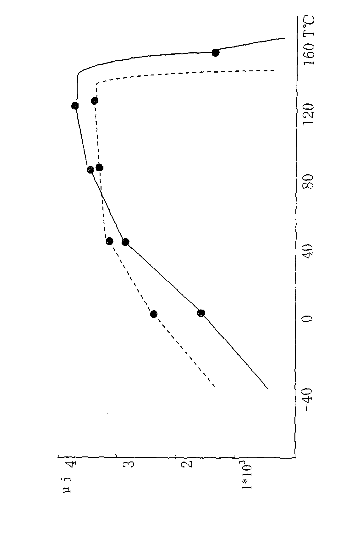
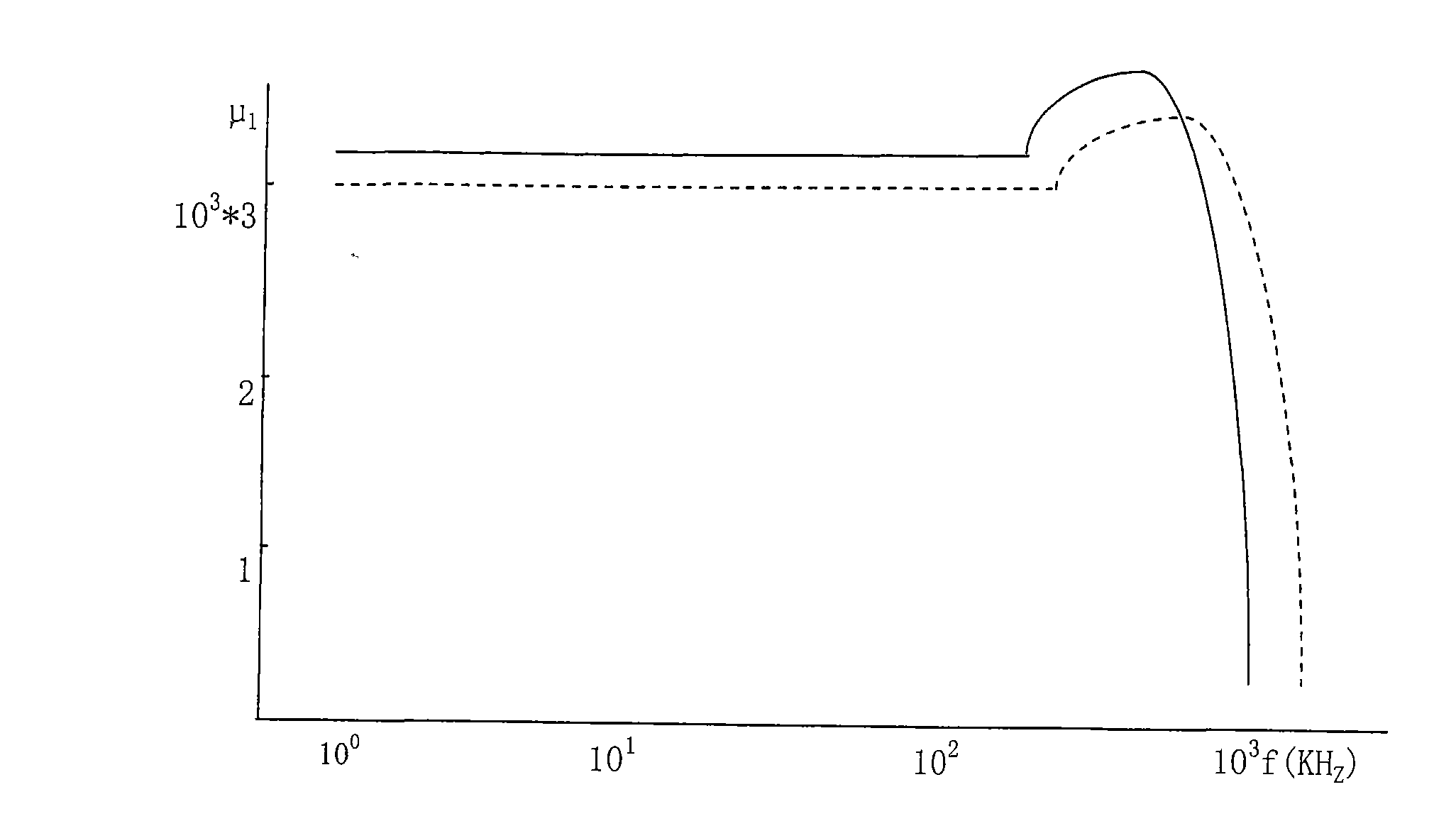
[0030] please see figure 1 ,according to figure 1 In the process flow shown, 52.8 mol% of iron oxide, 24.0 mol% of manganese oxide and 23.2 mol% of zinc oxide are converted into weight percentages and weighed as the main raw materials, which are put into the dry intensive mixer and mixed with each other for 60 minutes. The main raw materials are sent to the vibrating ball mill for 40 minutes to obtain fine powder, which is then sent to the electric rotary kiln for pre-calcination. Add 0.06wt% of titanium oxide, 0.08wt% of calcium oxide and 0.04wt% of molybdenum oxide which are selected and weighed as auxiliary raw materials, before adding the weighed auxiliary raw materials to the main raw materials First use a sand mill to grind the auxiliary raw materials for 110min. During the sand grinding process, the weight-to-volume ratio of control material (auxiliary raw materials): sanding balls: water is 1: 1: 0.6 (i.e. auxiliary raw materials and sanding balls and The proportion ...

Embodiment 2

[0036] Only iron oxide, manganese oxide and zinc oxide constituting the main raw material components were changed to Fe 2 o 3 52.5mol%, MnO23.5mol% and ZnO24.3mol%; the auxiliary raw material components titanium oxide, calcium oxide and molybdenum oxide were changed to TiO 2 0.065wt%, CaO0.085wt% and MoO 3 0.045wt%; change the mixing time of the main raw materials to 50min, and the vibration grinding time to 32min; change the pre-calcination temperature and time of the main raw materials to 975°C and 110min respectively; change the sanding time of the auxiliary raw materials to 120min; In the sintering of the blank, the heating rate from room temperature to 600°C was changed to 62°C / h, the heating rate was changed to 195°C / h from 600°C to 1360°C, and the holding time was changed to 3.9h. The cooling time from 1150°C to 1000°C was changed to 38min and the Image 6 air cooling shown. All the other are the same as the description to embodiment 1. The physical properties of t...

Embodiment 3

[0038] Change the iron oxide, manganese oxide and zinc oxide that constitute the main raw material components to Fe 2 o 3 53.4mol%, MnO23.9mol% and ZnO22mol%; the auxiliary raw material components titanium oxide, calcium oxide and molybdenum oxide were changed to TiO 2 0.07wt%, CaO0.08wt% and MoO 3 0.055wt%; change the mixing time and vibration grinding time of the main raw materials to 55min and 36min respectively; change the pre-calcination temperature and time of the main raw materials to 960°C and 120min respectively; In the sintering of the blank, the heating rate from room temperature to 600°C was changed to 58°C / h, and the heating rate was changed to 203°C / h when the temperature was above 600°C to 1345°C, and the holding time was changed to 4.2h. The cooling time from 1150°C to 1000°C was changed to 36 minutes and the Figure 5 Water cooling shown. All the other are the same as the description to embodiment 1. The physical properties of the obtained anti-electromag...


PUM


Abstract

The invention relates to an electromagnetic interference resistant Mn-Zn ferrite magnet material which belongs to the technical field of magnetic materials and processing thereof. The Mn-Zn ferrite magnet material contains main raw materials, including 52.5-53.6 mol percent of ferric oxide, 22.8-24.0 mol percent of manganese oxide and 21.5-24.3 mol percent of zinc oxide, and also contains auxiliary raw materials, including 500-1,200 ppm of titanium oxide, 700-1,000 ppm of calcium oxide and 200-800 ppm of molybdenum oxide which are added into the main raw materials. The invention can save energy, improve resistivity, reduce eddy-current loss, a magnetocrystallite anisotropy constant and hysteresis loss, and improve magnetic conductivity temperature, frequency characteristics and high-frequency performance. A good firing process curve is selected from a firing working procedure, and the Mn-Zn ferrite magnet material has favorable electromagnetic interference resistance.

Description

technical field [0001] The invention belongs to the technical field of magnetic materials and processing thereof, and in particular relates to a manganese-zinc ferrite magnet material resistant to electromagnetic interference, and also relates to a preparation method thereof. Background technique [0002] As is well known in the industry, manganese-zinc (MnZn) ferrite is the basic material of modern electronic industry and information industry. According to the application, MnZn ferrite can be divided into: power MnZn ferrite, high permeability MnZn ferrite (also known as high conductivity MnZn ferrite) and anti-electromagnetic interference MnZn ferrite. [0003] The aforementioned electromagnetic interference (English name: Electromagnetic Interference; abbreviated as EMI) refers to the interference generated by unwanted electromagnetic signals or noise signals on required electromagnetic signals. In today's electronic information age, with the rapid development of informa...

Claims


Application Information

Patent Timeline
Patent Type & Authority Applications(China)
IPC IPC(8): H01F1/36C04B35/28C04B35/622C04B35/64
Inventor 孟力丁伟清孟祥宇
Owner SUZHOU GUANDA MAGNET
Learn More