

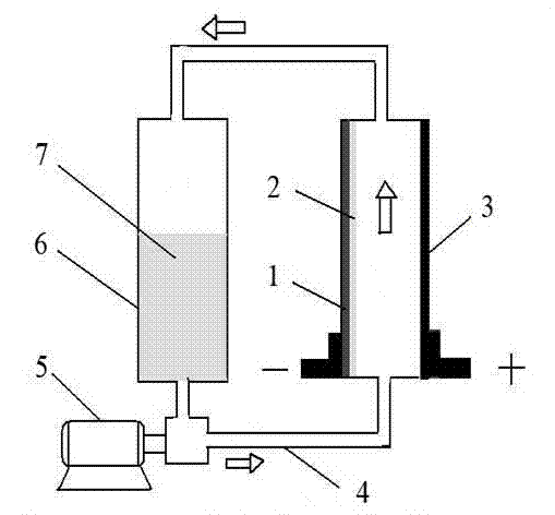
Acidic zinc single liquid flow energy storage battery
An energy storage battery, acid technology, applied in the field of energy storage technology and its electrochemical engineering, can solve problems such as hydrogen evolution self-discharge reaction, and achieve the effect of improving charge-discharge performance and corrosion resistance
- Summary
- Abstract
- Description
- Claims
- Application Information
AI Technical Summary
Problems solved by technology
Method used
Image

Examples
Embodiment 1
[0025] After mixing 30 grams of lead hydroxide and 5 grams of 20% NaOH solution evenly, apply it on 4×6cm 2 On the titanium plate frame, in 20% NaOH alkaline solution at 10mA / cm 2 The current density of the anodic oxidation is carried out to make it generate α-lead dioxide by electrodeposition reaction, and then the pure α-lead dioxide (29 grams) obtained by electrolysis is cleaned and crushed, and then 7 grams of β-lead dioxide and β-lead dioxide are added. After 4 grams of freshly prepared lead sulfate are mixed evenly, a paste is made and coated on a commercially available lead-antimony alloy grid to make an electrode plate for subsequent use.
[0026] Extrude 5 grams of expanded graphite and 95 grams of polyethylene plastic at 185°C to form a 4×6cm 2 The conductive electrode is electroplated with lead-indium-tin-copper alloy on its surface, and the mass percentage of the coating composition is 85:2:9:4. With the graphite electrode as negative pole, 500ml 1M ZnSO 4 -1M H...
Embodiment 2
[0028] The positive electrode is prepared according to the same manufacturing process as in Example 1. The base conductive material of the negative electrode of the battery is based on a specific lead-containing brass alloy sheet (mass percentage of alloy metal Zn:Cu:Pb=30:65:5) Material, cut into an area of 40×60mm 2 , an alloy sheet with a thickness of 0.5mm, then electroplate 0.006mm thick lead on its surface, and then electroplate a 0.004mm thick lead-indium-tin-copper alloy layer with acid corrosion resistance and good conductivity on its surface, its The mass percentage of the coating composition is 85:2:9:4. Finally, the above-mentioned electrode matrix is subjected to electrodeposition reaction in a composite acidic zinc sulfate electrolyte containing corrosion inhibition, and an electrolytic zinc layer with a thickness of 1.5 mm is electrodeposited to obtain a composite zinc negative electrode.
[0029] Take 500ml 1M ZnSO 4 -1.5M H 2 SO 4 -1M NaSO 4 -0.5g / L D...
Embodiment 3
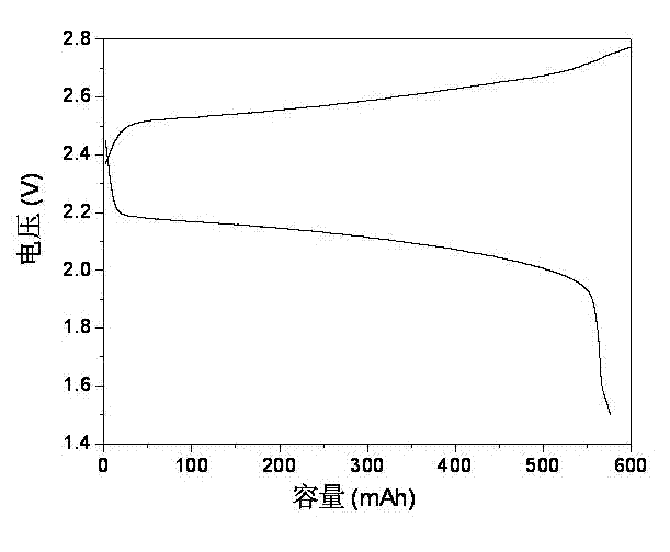
[0031] The mixture of 65 grams of lead hydroxide and 40 grams of sodium hydroxide is carried out oxidation reaction in 200ml NaClO (available chlorine>19%) solution, and wherein lead hydroxide is oxidized into 60 grams of α-lead dioxide, then according to embodiment 1 same The method makes lead dioxide positive electrode. The negative electrode of the battery is made of reinforced polypropylene plastic with a thickness of 1mm, and a layer of metal copper with a thickness of 0.002mm is plated on the surface by ordinary electroless plating method, and then a 0.008mm thick lead-indium- Tin-copper alloy, the mass percentage of its coating composition is 85:2:9:4. The battery uses 1500ml 1M ZnSO 4 -1.5M H 2 SO 4 -0.5g / L manganese sulfate mixed solution is used as the electrolyte, and the HL-4B peristaltic pump is used as the power pump to circulate the electrolyte at a speed of 600 ml / h. 2 The current density can provide a discharge voltage of 2.05-2.15V, resulting in a capacit...
PUM
 Abstract
Description
Claims
Application Information