Energy self-feed type fluidized bed sludge incineration and tail gas pollution control system

A technology for sludge incineration and pollution control, applied in dehydration/drying/concentrated sludge treatment, incinerators, combustion methods, etc., can solve uneven heat transfer between partitions, uneconomical energy saving, and limited heating effect of wet sludge and other issues to achieve the effect of harmless

Active Publication Date: 2011-11-23
BRIGHT THERMAL EQUIP CO LTD
View PDF13 Cites 19 Cited by
  • Summary
  • Abstract
  • Description
  • Claims
  • Application Information

AI Technical Summary

Problems solved by technology

[0005] Invention patent CN200410086312.5 "a wet sludge incineration treatment method and incineration treatment device", invention patent CN200510038416.3 "sludge incineration treatment method and sludge incineration treatment process", discloses that wet sludge with a water content of 70-80% The mud is directly sent to the incinerator for combustion, which has a great impact on the stable combustion in the furnace, and requires the burning of a large amount of auxiliary fuel, which is uneconomical from the perspective of energy conservation.
[0006] Invention patent CN200610037604.9 "Urban sludge fluidized bed incineration device and method" and invention patent CN200710060213.3 "Wet sludge circulating fluidized bed harmless incineration integrated treatment process", discloses a sludge incineration process, However, for the sewage problem and acid gas (HCl, SO 2 ), heavy metals and dioxin control measures are not mentioned
[0007] The utility model patent CN20082012330.x discloses a wet sludge drying and incineration treatment device, which se...

Method used


Image

  • Energy self-feed type fluidized bed sludge incineration and tail gas pollution control system
  • Energy self-feed type fluidized bed sludge incineration and tail gas pollution control system

Examples


Embodiment 1

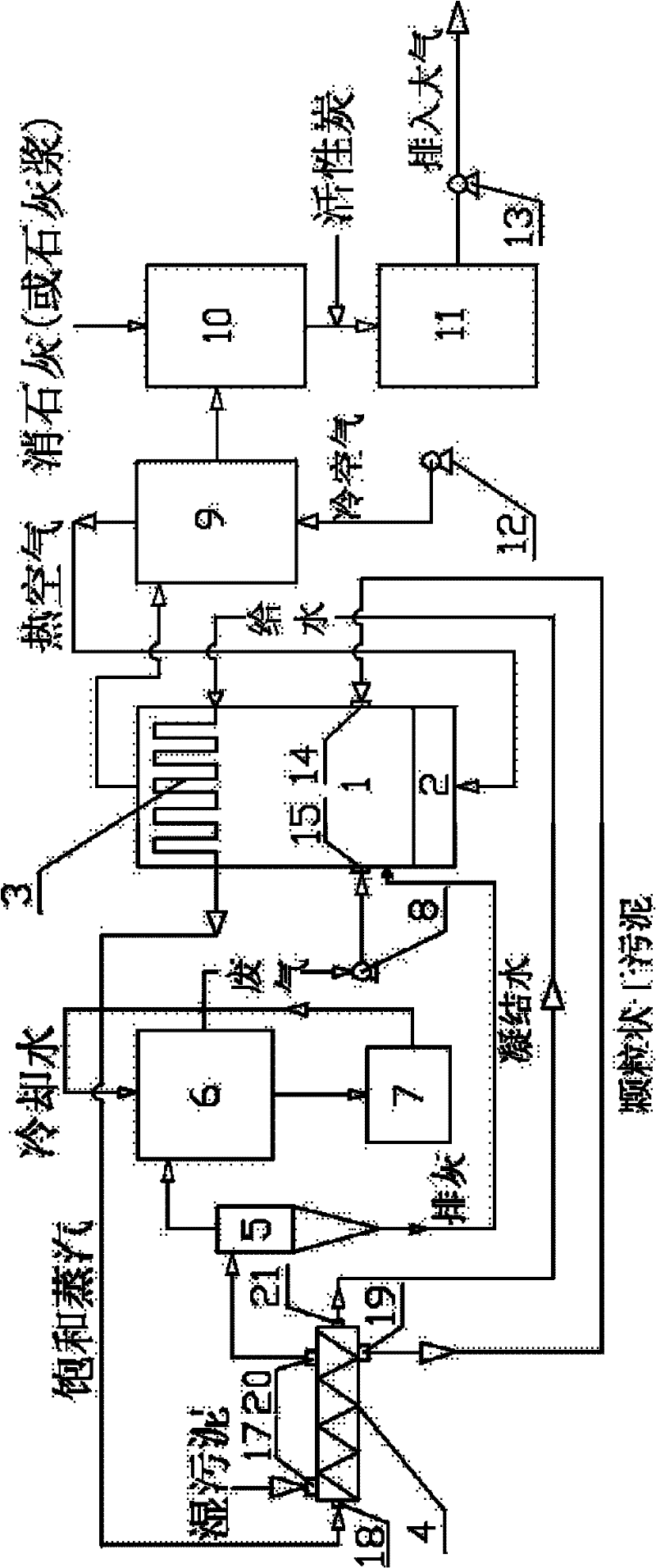
[0026] Example 1: see figure 1 , the control system includes fluidized bed incinerator 1, air chamber 2, waste heat boiler 3, sludge dryer 4, separator 5, spray dehydration tower 6, sewage treatment tank 7, fan 8, air preheater 9, acid Gas absorption tower 10, bag filter 11, blower 12 and induced draft fan 13. The fluidized bed incinerator 1 is equipped with a dry sludge feed port, the upper part is arranged with a waste heat boiler 3, and the lower part is arranged with an air chamber 2. The hot air from the air preheater enters the air chamber 2, and then enters the incinerator to participate in combustion. The steam generated by the waste heat boiler 3 is connected to the steam inlet 18 of the sludge dryer 4 through pipelines. The sludge dryer 4 is a paddle dryer, which is provided with a wet sludge inlet 17, a steam inlet 18, a dry sludge outlet 19 and Exhaust gas outlet 20 and condensed water outlet 21, the water content of the wet sludge after drying drops from 80% to a...

Embodiment 2

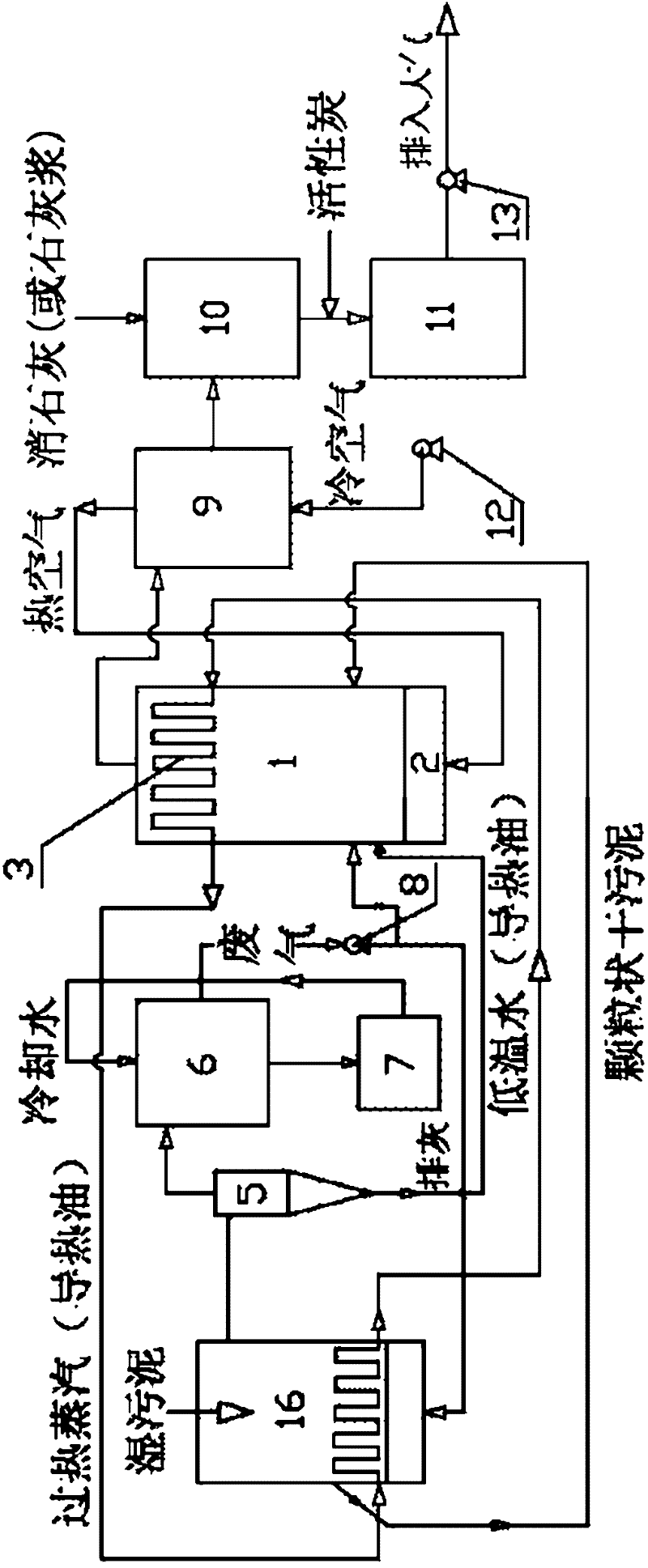
[0028] Example 2: see figure 2 , In this embodiment, the sludge dryer 4 for drying wet sludge can also be replaced by a fluidized bed dryer 16, and the fluidized bed sludge drying technology is a mature technology in the present. In this embodiment, the circulating working fluid used to dry the wet sludge can be superheated steam (temperature greater than 300° C.) or heat transfer oil. The fluidized medium of the fluidized bed dryer 16 is dehydrated waste gas produced by drying wet sludge. When the dehydrated waste gas is more than the amount of gas required for fluidization, the excess can be sent to the incinerator for combustion and deodorization.


PUM


Abstract

The invention relates to an energy self-feed type fluidized bed sludge incineration and tail gas pollution control system. The system comprises a fluidized bed incinerator, a waste heat boiler, a sludge dryer, a separator, a spray dehydrating tower, a sewage treatment pool, an air preheater, an acid air absorption tower, a bag-type dust collector, an air blower and an induced draft fan. Wet sludge is dried in the dryer (a heat source is steam produced through combustion of dried sludge), and the dried sludge (granular) is conveyed into a fluidized bed and combusted; as the calorific value of the dried sludge is high, the normal combustion can be kept, and the heat produced through combustion is used for drying the wet sludge, so that an energy conversion process is finished. Waste air which contains water vapor and comes from the dryer is sprayed and dehydrated by a spray condensation tower and then is conveyed into a fluidized bed and is combusted. The self feed of sludge incineration energy can be realized, the waste water and waste air produced at each treatment section can be subjected to deodorization and innocent treatment, and the system has the advantages of high energy utilization rate, good treatment effect, and the like, and a small amount of pollutant is discharged.

Description

technical field [0001] The invention relates to environmental protection equipment, in particular to an energy self-sufficient fluidized bed sludge incineration and tail gas pollution control system. Background technique [0002] The annual dry sludge produced by urban sewage treatment plants in my country is about 25×10 4 t, based on wet sludge, is about 450~550×10 4 t, and grow at a rate of about 15% per year. Sludge contains a large amount of organic matter and rich nitrogen, phosphorus and other nutrients. Arbitrary discharge into the water body will consume a large amount of oxygen in the water body, resulting in deterioration of water quality and seriously affecting the survival of aquatic organisms; the nutrients in the sludge are also It will cause eutrophication of the water body and a large number of algae, thereby deteriorating the water quality and reducing the fishery output; in addition, there are many toxic substances, heavy metals, pathogenic bacteria, para...

Claims


Application Information

Patent Timeline
IPC IPC(8): F23G7/00F23J15/04F23L15/00C02F11/12
CPCY02E20/34
Inventor 徐智明
Owner BRIGHT THERMAL EQUIP CO LTD
Why Eureka
Try Eureka