Molded inorganic-fiber object and process for producing same

一种无机纤维、成型体的技术,应用在制造工具、陶瓷成型机、非织造布等方向,能够解决载重弱、纤维飞散、堆积粒子状物质等问题,达到耐高速风蚀性优异、抗机械冲击性优异、物性平衡优异的效果

Active Publication Date: 2014-05-07
MAFTEC CO LTD
View PDF12 Cites 15 Cited by
  • Summary
  • Abstract
  • Description
  • Claims
  • Application Information

AI Technical Summary

Problems solved by technology

[0003] However, inorganic fibers are generally aggregates of fibers having various lengths, and conventional inorganic fiber molded articles obtained by slurrying such inorganic fibers only with binder components, dehydration molding, and firing , there are the following problems: under the action of mechanical shock and thermal shock during cutting or use, cracks will occur on the surface, and inorganic fibers and particulate matter on the surface of the molded body will fall off and scatter
In addition, it is known that when fibers made of silica-based raw materials are exposed to temperatures above 1000°C, cristobalite, which is harmful to the human body, is produced.
The problem of the scattering of these fibrous and particulate matter and the generation of harmful substances is not preferable in terms of maintaining the working environment
Moreover, when cracks are generated due to thermal shock or mechanical shock, if the inorganic fibers are partially detached, the function as a heat insulating material may be lost.
[0005] On the other hand, when the needling-punched inorganic fiber aggregates are processed directly into a block and constructed as a heat insulating material for a high-temperature furnace, although the thermal shock resistance is excellent, there is a problem that when using high-velocity gas Under the conditions of high wind velocity burners such as burners, surface wind erosion and fiber scattering will occur due to the influence of wind velocity
However, there is a problem that when used at a high temperature, the glass layer is peeled off from the base material of the inorganic fiber molded body due to thermal expansion, or cracks are generated.
However, this method has problems such as insufficient solidification of the coating and the inorganic fiber molded body depending on the conditions of use, and peeling of the coating due to thermal shock or mechanical shock.
[0008] In addition, in any of the above-mentioned techniques, since the inorganic fiber molded body itself is molded by dehydration molding of a slurry using fibrillated fibers, there is a problem that as a material structure, the load against bending, etc. , handling, vibration during use, etc., will cause fracture, and it is also weak to thermal shock
However, in this method, first of all, there is a problem that it is difficult to make a thick heat insulating material
[0010] Also, in this method, there is a problem that the impregnated binder migrates to the vicinity of the surface of the inorganic fiber aggregate during drying of the inorganic fiber aggregate containing the binder.
That is, when a thick heat insulating material is produced by laminating thinner mat-shaped inorganic fiber aggregates by using this method, even if the dried thinner mat-shaped inorganic fiber aggregates are stacked, the bonding of the overlapping surfaces will not be sufficient. Sufficient, therefore, there is not only the problem of easy delamination due to thermal shock, but also the following problems: compared with the laminated layers, particulate matter is easy to accumulate on the surface of the molded body, and the particulate matter is easy to fall off due to mechanical impact.
[0013] However, in this inorganic fiber molded article, there is the following problem: an organic binder is used in the slurry, and in the case of a large amount of slurry, it must be pre-baked. In the case of pre-baking, it is easy to generate cracks at a relatively low temperature

Method used


Image

  • Molded inorganic-fiber object and process for producing same
  • Molded inorganic-fiber object and process for producing same
  • Molded inorganic-fiber object and process for producing same

Examples


preparation example Construction

[0091] [Preparation of spinning solution]

[0092] Basic Aluminum Chloride: Al(OH) 3-x Cl x For example, it can be prepared by dissolving metallic aluminum in aqueous hydrochloric acid or aluminum chloride. The value of x in the above chemical formula is usually 0.45 to 0.54, preferably 0.5 to 0.53. As the silicon compound, silica sol is preferably used, and a water-soluble silicon compound such as tetraethyl silicate or a water-soluble siloxane derivative may also be used. As the organic polymer, for example, water-soluble polymer compounds such as polyvinyl alcohol, polyethylene glycol, and polyacrylamide are preferably used. Their degree of polymerization is usually 1000-3000.

[0093] For the spinning solution, the ratio of aluminum derived from basic aluminum chloride to silicon derived from the silicon compound is preferably expressed in terms of Al 2 o 3 and SiO 2 The mass ratio of aluminum is usually 99:1-65:35, preferably 99:1-70:30, the concentration of alumin...

Embodiment 1 and 2

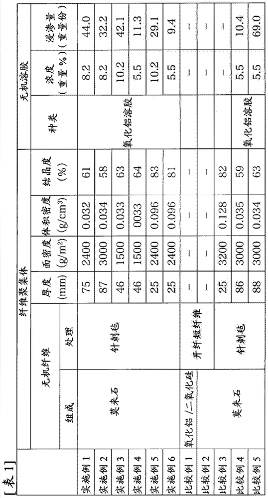
[0152] An aqueous basic aluminum chloride solution having an aluminum concentration of 170 g / L and an Al / Cl (atomic ratio) of 1.8 was prepared. The aluminum content was quantified by chelate titration using EDTA. Next, silica sol and polyvinyl alcohol were added to the above aqueous solution, and then concentrated to obtain the ratio of aluminum to silicon (Al 2 o 3 and SiO 2 weight ratio) is 72:28, the total mass concentration of alumina and silica converted into oxide mass is about 30% by mass, and the viscosity is 40 poise (measured value using a rotational viscometer at 25°C). silk liquid. The spinning solution was spun by the blowing method, and then bundled to obtain a mat-shaped fiber aggregate of an alumina / silica-based fiber precursor. After needle-punching the mat-like fiber aggregate, it was fired at 1200°C to obtain a polycrystalline alumina / silica-based fiber aggregate (hereinafter, sometimes referred to as " Original cloth"). In addition, the above-mentione...

Embodiment 3~6

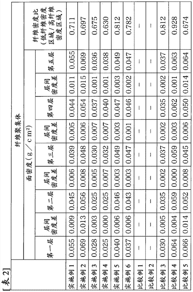
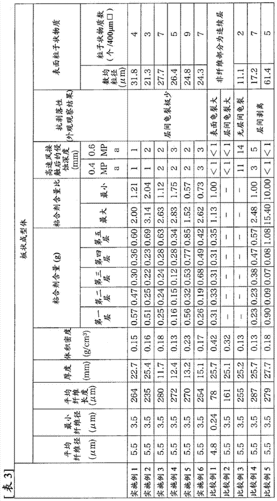
[0163] In Example 1, except that the original fabric was not laminated, and a single layer with the thickness, surface density, and bulk density shown in Table 1 was used, the same operation was performed as in Example 1, and the plate-shaped inorganic fiber molding shown in Table 3 was obtained. body. The compression height was divided into 5 equal parts for the first layer to the fifth layer. The surface density of each layer obtained, the density difference between the layers, and the fiber density ratio (low fiber density area / high fiber density area) are as follows: Table 2 shows. In Embodiment 3 and Embodiment 4, the first layer, the second layer and the third layer are low fiber density regions, and the fourth layer and fifth layer are high fiber density regions. Furthermore, in Example 5 and Example 6, the first layer is a low fiber density region, and the second to fifth layers are high density fiber regions. Table 3 shows the evaluation results of the obtained plat...


PUM

PropertyMeasurementUnit
particle diameteraaaaaaaaaa
diameteraaaaaaaaaa
surface densityaaaaaaaaaa

Abstract

Provided is a molded inorganic-fiber object which is characterized by being extremely lightweight, being reduced in flying of fibers or a particulate substance from the surface thereof, and being free from problems concerning environmental pollution, such as generation of a harmful substance. The molded object is excellent in terms of thermal shock resistance and mechanical shock resistance and of resistance to high-speed wind erosion, has an excellent balance among material properties, and can be used in various heat insulator applications. The molded inorganic-fiber object comprises inorganic fibers and inorganic binder particles and has at least a pair of regions, a high-fiber-density region and a low-fiber-density region, wherein the ratio of the content of the binder particles in the high-fiber-density region to the content thereof in the low-fiber-density region, as determined by a given method, is 0.5:1 to 5:1 and the inorganic binder particles in the outermost surface of the molded object have a number-average particle diameter, as determined by a given method, of 20-35 [mu]m, the number of the inorganic binder particles therein being less than 15.

Description

technical field [0001] The present invention relates to an inorganic fiber molded product and a method for producing the same. Specifically, it relates to a product that is extremely light in weight, has excellent thermal shock resistance and mechanical shock resistance, and does not cause scattering of fibers and particulate matter in handling. Inorganic fiber molded body used as cladding materials such as the inner wall of various industrial furnaces or molten metal ladle covers, heat insulating materials for conveying systems, and heat insulating materials such as furnace tiles, and a method for manufacturing the inorganic fiber molded body . Background technique [0002] Conventionally, as an inorganic fiber molded body, it is known that inorganic fibers such as alumina fibers, silica fibers, and a slurry containing inorganic particles, inorganic binders, and organic binders are dehydrated and then fired. Inorganic fiber moldings. Since the inorganic fiber molded body ...

Claims


Application Information

Patent Timeline
Patent Type & Authority Applications(China)
IPC IPC(8): D04H1/42F27D1/00
CPCF27D1/0006D04H1/4209C04B35/111C04B2235/5228C04B2235/526C04B2235/5264C04B2235/606C04B2235/608C04B2235/616C04B2235/77C04B2235/786C04B2235/96Y10T428/24992F27D2001/0073F27D1/0009C04B35/80B28B23/0081F01N3/2864
Inventor 福井刚史伊藤敏男秦雄作青柳久志伊藤秀高
Owner MAFTEC CO LTD
Why Eureka
Try Eureka