
Nitrogenous light-emitting particle, nitrogenous light-emitting particle preparation method, nitrogenous light emitter and light emitting device

A technology of luminescent particles and luminescent crystals, which is applied to optical elements, semiconductor devices, and luminescent materials used to change the spectral characteristics of emitted light, and can solve the problem of decreased luminous intensity of phosphor powder, low luminous efficiency of phosphor powder, and weak energy conversion efficiency. Low-level problems, to achieve solid and stable crystal structure, good anti-aging and light-fading properties, and excellent anti-aging and light-fading effects

Active Publication Date: 2016-06-01
JIANGSU BREE OPTRONICS CO LTD
View PDF2 Cites 8 Cited by
  • Summary
  • Abstract
  • Description
  • Claims
  • Application Information

AI Technical Summary

Problems solved by technology

The existing methods for manufacturing white LEDs mainly include: first, coating yellow phosphor (YAG) on the blue LED chip to realize white light emission, but YAG phosphor has the disadvantages of high coloring temperature and low color rendering index, which cannot satisfy Requirements for semiconductor lighting; although the emission spectrum of YAG phosphor is very wide, the emission intensity in the red light region is very weak, resulting in the lack of red light after mixing with blue LED chips, thus affecting the correlated color temperature and color rendering of white LEDs index
The second is to apply green and red phosphors on the blue LED chips to solve the above problems, but red phosphors also have many problems, such as CaS:Eu 2+ Large light attenuation, poor chemical stability, CaMoO 4 :Eu 2+ Narrow excitation range, Y 2 o 3 :Eu 3+ and Y 2 o 2 S:Eu 3+ Weak absorption in the blue light region and low energy conversion efficiency, M 2 Si 5 N 8 :Eu 2+ The anti-light decay performance is poor, and it cannot be perfectly matched with the LED chip. These are the bottlenecks that restrict the development of white LED technology.
The third is to quote CaAlSiN 3 Although the overall performance of nitride phosphors with a crystal structure is better than that of the aforementioned YAG phosphors and ordinary red phosphors, there are still the following obvious deficiencies: ①Due to the influence of component diffusion, nucleation and preferred growth orientation during the synthesis of phosphors The internal law of the primary grain size has not been fully studied, resulting in low luminous efficiency of phosphors, so the luminous efficiency needs to be further improved; ② Phosphors will deteriorate under the combined effects of high optical density, high temperature and high humidity. It directly leads to the decline of the overall lighting effect, especially the large drift of the color coordinates, so the durability of the phosphor cannot fully meet the requirements of general lighting.
However, there are still obvious deficiencies in this method, because (Sr,Ca)AlSiN is prepared by the alloy method. 3 Red phosphor emphasizes on controlling the lower oxygen content to achieve higher consistency and phase purity, which significantly reduces the durability of the phosphor and poor practicability, which limits its application
[0006] "Reduced thermal degradation of othered-emitting Sr" published by Journal of Materials Chemistry C in 2015 2 Si 5 N 8 :Eu 2+ Phosphorviathermaltreatmentinnitrogen", for Sr 2 Si 5 N 8 :Eu 2+ The thermal degradation mechanism of the phosphor was studied, and it was believed that a layer of oxide protective film was formed on the surface of the phosphor by baking, which prevented the Eu 2+ Oxidation of , improves the thermal deterioration performance, and it is speculated that it can improve the Sr 2 Si 5 N 8 :Eu 2+ The application performance in LED, but there is no support from experimental data, and it has not fundamentally solved the problem of Sr 2 Si 5 N 8 :Eu 2+ long-term aging problems
In fact, in this system, due to the Sr 2 Si 5 N 8 :Eu 2+ The stability itself is poor, and the surface crystal structure is destroyed during the firing process, resulting in a significant decrease in the luminous intensity of the phosphor, so it has no practical application value
[0007] To sum up, there are contradictions in the existing technology in solving the problem of anti-aging and light decay of nitride phosphors and improving the luminous efficiency of phosphors. The basic rule is to improve the anti-aging and light decay of phosphors at the cost of reducing the luminous efficiency of phosphors. performance, or at the expense of reducing the anti-aging and light-fading performance of phosphors to improve the luminous efficiency of phosphors. At present, there is no comprehensive solution that can neither reduce the luminous efficiency of phosphors but also improve the anti-aging and light-fading performance of phosphors.

Method used


Image

  • Nitrogenous light-emitting particle, nitrogenous light-emitting particle preparation method, nitrogenous light emitter and light emitting device
  • Nitrogenous light-emitting particle, nitrogenous light-emitting particle preparation method, nitrogenous light emitter and light emitting device
  • Nitrogenous light-emitting particle, nitrogenous light-emitting particle preparation method, nitrogenous light emitter and light emitting device

Examples


preparation example Construction

[0051] A preparation method 1 of a nitrogen-containing luminescent particle and its preferred solution proposed by the present invention includes the following specific steps:

[0052] Step 1: Use the nitrides, oxides or halides of M, A, B, R as raw materials, according to the general chemical formula M m-m1 A a1 B b1 o O1 N n1 :R m1 The stoichiometric ratio of the cations in the composition weighs the required raw materials;

[0053] Step 2: mixing the raw materials weighed in step 1 uniformly in a nitrogen atmosphere to form a mixture;

[0054] Step 3: Roast the mixture obtained in step 2 at a high temperature in a roasting atmosphere, then cool down to a predetermined temperature, and then pass in nitrogen-oxygen mixed gas or air for low-temperature roasting to obtain a semi-finished product of nitrogen-containing luminescent particles;

[0055] Wherein: the high-temperature calcination temperature is 1400-2000°C, and the high-temperature calcination time is 6-18h; th...

Embodiment 1

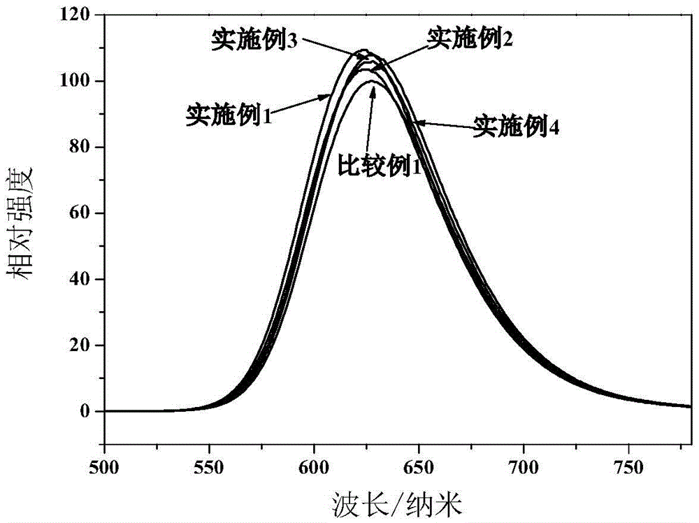
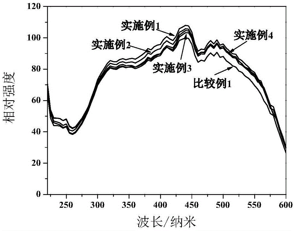
[0069] Weigh Ca 3 N 2 0.27g, Sr 3 N 2 9.954g, AlN4.477g, Si 3 N 4 5.107g, Eu 2 o 3 0.192g, the above raw materials were fully mixed in a nitrogen atmosphere for 3 hours, put into a molybdenum crucible, and then quickly moved into a tube furnace, and then gradually heated up to 1700°C under the protection of a nitrogen atmosphere, and kept for 12 hours; After the particles are crushed and sieved, put the sifted nitrogen-containing luminescent particles into deionized water and stir for 30 minutes, then filter with suction, and finally wash until the conductivity is 8.56μs / cm. After drying, heat up to 400°C, the calcination time is 5h, and the finished nitrogen-containing luminescent particles can be produced. For the emission spectrum see figure 2 , the excitation spectrum is shown in image 3 , X-ray diffraction pattern see Figure 4 . The chemical composition of the oxygen-poor region of nitrogen-containing luminescent particles is Ca 0.05 Sr 0.94 AlSiN 3 :0.01...

Embodiment 2

[0071] Weigh Ca 3 N 2 0.435g, Sr 3 N 2 9.712g, AlN4.512g, Si 3 N 4 5.147g, Eu 2 o 3 0.194g, the above raw materials were fully mixed in a nitrogen atmosphere for 3 hours, put into a molybdenum crucible, and then quickly moved into a tube furnace, and then gradually heated to 1700°C under the protection of a nitrogen atmosphere, and kept for 12 hours; After the particles are crushed and sieved, put the sifted nitrogen-containing luminescent particles into deionized water and stir for 30 minutes, then filter with suction, and finally wash until the conductivity is 4.42μs / cm. After drying, heat up to 400°C, the calcination time is 5h, and the finished nitrogen-containing luminescent particles can be produced. For the emission spectrum see figure 2 , the excitation spectrum is shown in image 3 , X-ray diffraction pattern see Figure 4 . The chemical composition of the oxygen-poor region of nitrogen-containing luminescent particles is Ca 0.08 Sr 0.91 AlSiN 3 :0.01Eu...


PUM

PropertyMeasurementUnit
wavelengthaaaaaaaaaa

Abstract

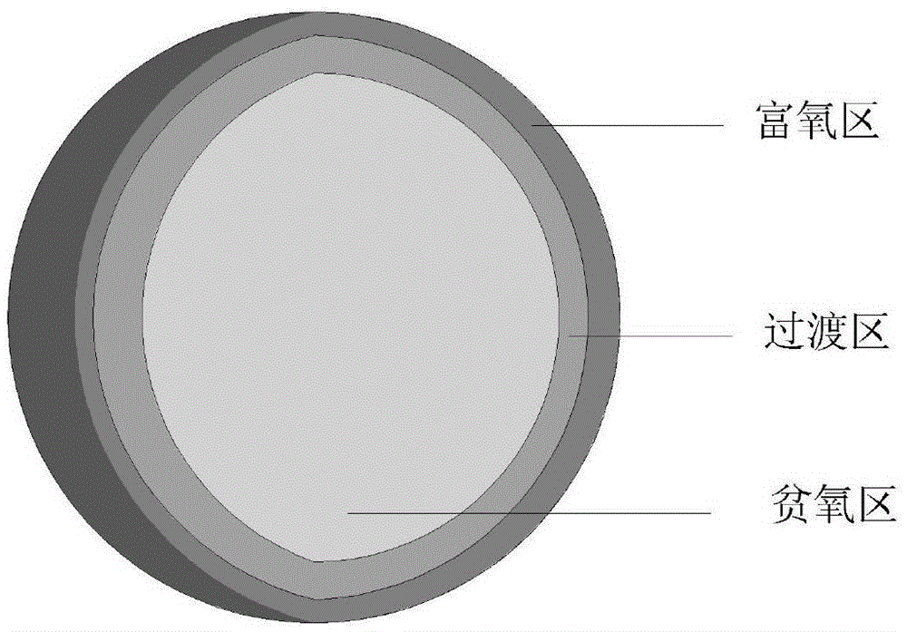
The invention relates to a nitrogenous light-emitting particle. The nitrogenous light-emitting particle is characterized by structurally comprises an oxygen-deficient region, a transition region and an oxygen-rich region sequentially from the core of the particle to the outer surface along with progressive oxygen content increase. The oxygen-deficient region mainly comprises nitride light-emitting crystal or oxygenous solid solution thereof, the transition region mainly comprises an oxynitride material, and the oxygen-rich region mainly comprises an oxide material or an oxynitride material. The nitride light-emitting crystal or oxygenous solid solution thereof refers to Mm-m1Aa1Bb1Oo1Nn1:Rm1, the oxynitride material refers to Mm-m2Aa2Bb2Oo2Nn2:Rm2, and the oxide material or the oxynitride material refers to Mm-m3Aa3Bb3Oo3Nn3:Rm3. The nitrogenous light-emitting particle and a nitrogenous light emitter are high in chemical stability, excellent in resistance to aging and light attenuation and high in light emitting efficiency and are applicable to various light emitting devices. The preparation method is simple, convenient and reliable and is suitable for industrial batch production.

Description

technical field [0001] The invention belongs to the technical field of LED phosphors and light-emitting devices, and in particular relates to a nitrogen-containing luminescent particle that can be effectively excited by ultraviolet light, purple light or blue light, a preparation method thereof, a nitrogen-containing luminescent body and a light-emitting device. Background technique [0002] Today's semiconductor lighting electric light source represented by light-emitting diode (LED) is known as the fourth generation of lighting electric light source after incandescent lamps, fluorescent lamps and energy-saving lamps, and is called "21st century green light source". [0003] As semiconductor lighting enters the field of general lighting, it is imminent to accelerate the development of white LEDs with high color rendering, anti-aging and low light decay. The existing methods for manufacturing white LEDs mainly include: first, coating yellow phosphor (YAG) on the blue LED chi...

Claims


Application Information

Patent Timeline
Patent Type & Authority Applications(China)
IPC IPC(8): C09K11/64H01L33/50F21V9/16
CPCF21V9/30C09K11/0883C09K11/7734H01L33/502C09K11/77348C01B21/0602C01B21/0823C01P2002/72C01P2002/84C01P2004/03Y02B20/00C09K11/77C09K11/7728H01L33/501C09K11/55C09K11/592C09K11/64C09K11/0816C09K11/0822H01L33/50
Inventor 何锦华滕晓明梁超符义兵
Owner JIANGSU BREE OPTRONICS CO LTD
Learn More