Ceramic heat barrier coating having low thermal conductivity, and process for the deposition of said coating

a heat barrier coating and ceramic technology, applied in the direction of chemical vapor deposition coating, machine/engine, natural mineral layered products, etc., can solve the problems of differential expansion of metal and ceramic, limited approach, and inability of turbine components such as diffusers to withstand high temperatures, so as to prevent heat conduction through the deposit and reduce the difficulty of application

Inactive Publication Date: 2001-07-19
SN DETUDE & DE CONSTR DE MOTEURS DAVIATION S N E C M A
View PDF0 Cites 5 Cited by
  • Summary
  • Abstract
  • Description
  • Claims
  • Application Information

AI Technical Summary

Benefits of technology

[0005] Heat barrier technology consists of coating the components with a thin insulating ceramic layer varying in thickness from a few tens of micrometers to a few millimeters. The ceramic layer typically consists of zirconia stabilised with yttrium and has the advantages of low thermal conductivity and the good chemical stability necessary in the severe conditions experienced during turbine operation. A bonding sublayer of an aluminoforming metal alloy can be interposed between the superalloy and the ceramic layer and serves to boost the adhesion of the ceramic layer while protecting the substrate from oxidation.
[0007] Heat spraying and physical deposition in the vapour phase of an electron beam, called EB-PVD (electron beam physical vapour deposition) for short, are the two industrial processes used to deposit the heat barriers. For application to the aerodynamic part of the blades and diffusers the EB-PVD method is preferred to heat spraying, mainly because it gives a coating with a better surface texture and reduces obstruction of the ventilation apertures. Also, the EB-PVD process helps to provide the layer with a 
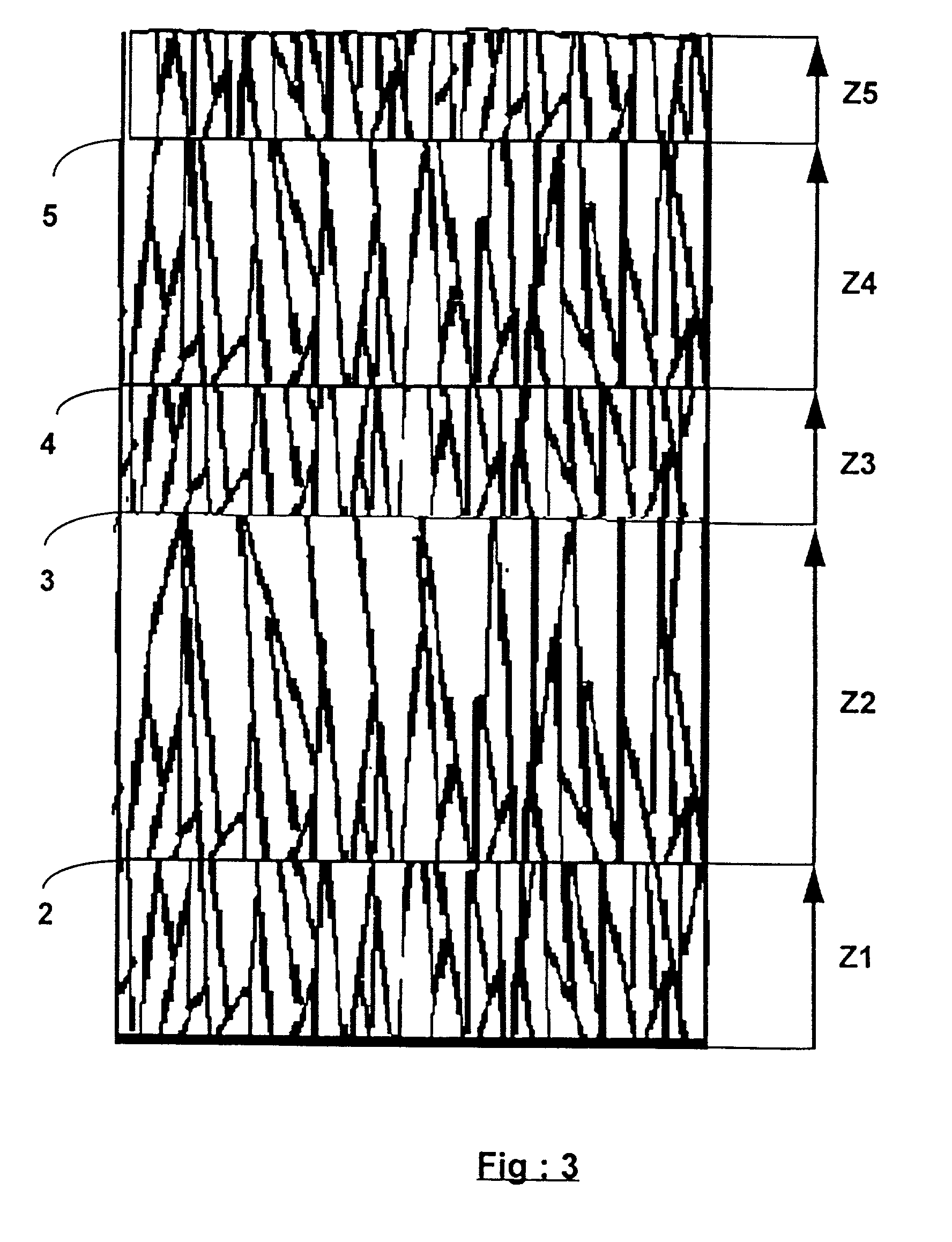
microstructure in the form of microcolumns perpendicular to the article surface. The microstructure enables the coating to deal with thermal and mechanical deformations in the plane of the substrate. For this reason EB-PVD heat barriers have a thermomechanical fatigue life which is considered to be better than that of plasma-sprayed ceramic layers.
[0008] In vapour deposition processes the coating is the result of vapour condensing on the article to be covered. There are two categories of vapour phase processes--physical processes (PVD) and chemical processes (CVD). In physical vapour phase processes the coating vapour is produced by vaporization of a solid material, also called the target. Vaporization can be produced by evaporation caused by a heat source or by cathodic atomization, a process in which the material is atomized by ionic bombardment of the target. In chemical vapour phase processes the coating vapour is the result of a 
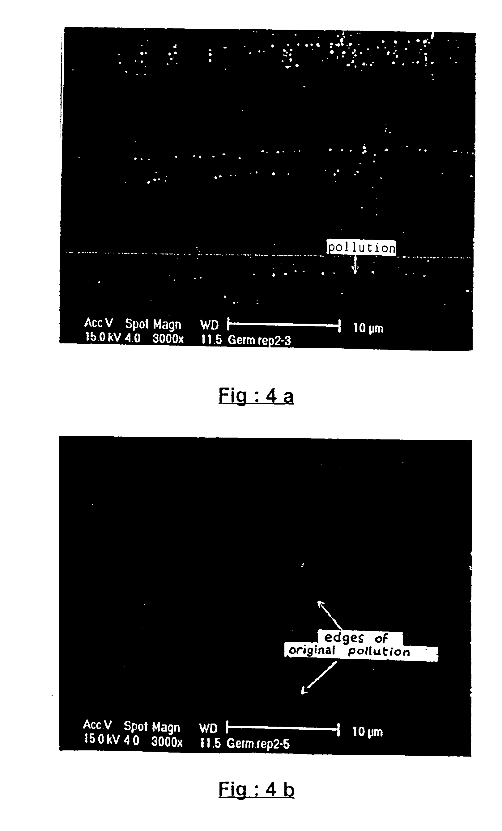
chemical reaction between the gaseous components, which occurs either in the vapour phase or at the coating / gas interface. The vapour phase deposition processes are carried out in a controlled atmosphere to prevent contamination or pollution of the deposits by reaction with unwanted gas components. To this end, the deposition chamber is preliminarily exhausted to a secondary vacuum (between 10.sup.-6 Torr and 10.sup.-4 Torr) and baked. An inert or reactive working gas can be introduced in a controlled manner during deposition.
[0011] Some of the oxygen thus dissociated from the zirconium oxide molecules is lost as a result of the pumping of the chamber, with the consequence that the zirconia deposits are rendered substoichiometric (oxygen depleted). This effect can be countered by the introduction of an oxygen-rich gas (typically a mixture of argon and oxygen) at a pressure of a few milli-Torr into the chamber during the deposition. The effect can also be corrected ex-situ when no reactive gas is introduced into the chamber during deposition. The stoichiometry of the coating is then restored by subjecting the coated articles to a simple annealing in air at a temperature of 700.degree.C. for 1 hour. The introduction of oxygen into the EB-PVD chamber also helps to preoxidise the articles in situ before the ceramic deposition. The alumina film thus formed on the surface of the bonding sublayer provides satisfactory adhesion of the ceramic layer. In the industrial EB-PVD process only those article surfaces facing the vaporization source are coated. To cover an article of a complex geometrical shape, such as a rotor blade or a diffuser, the article must be rotated in the flow of coating vapour.
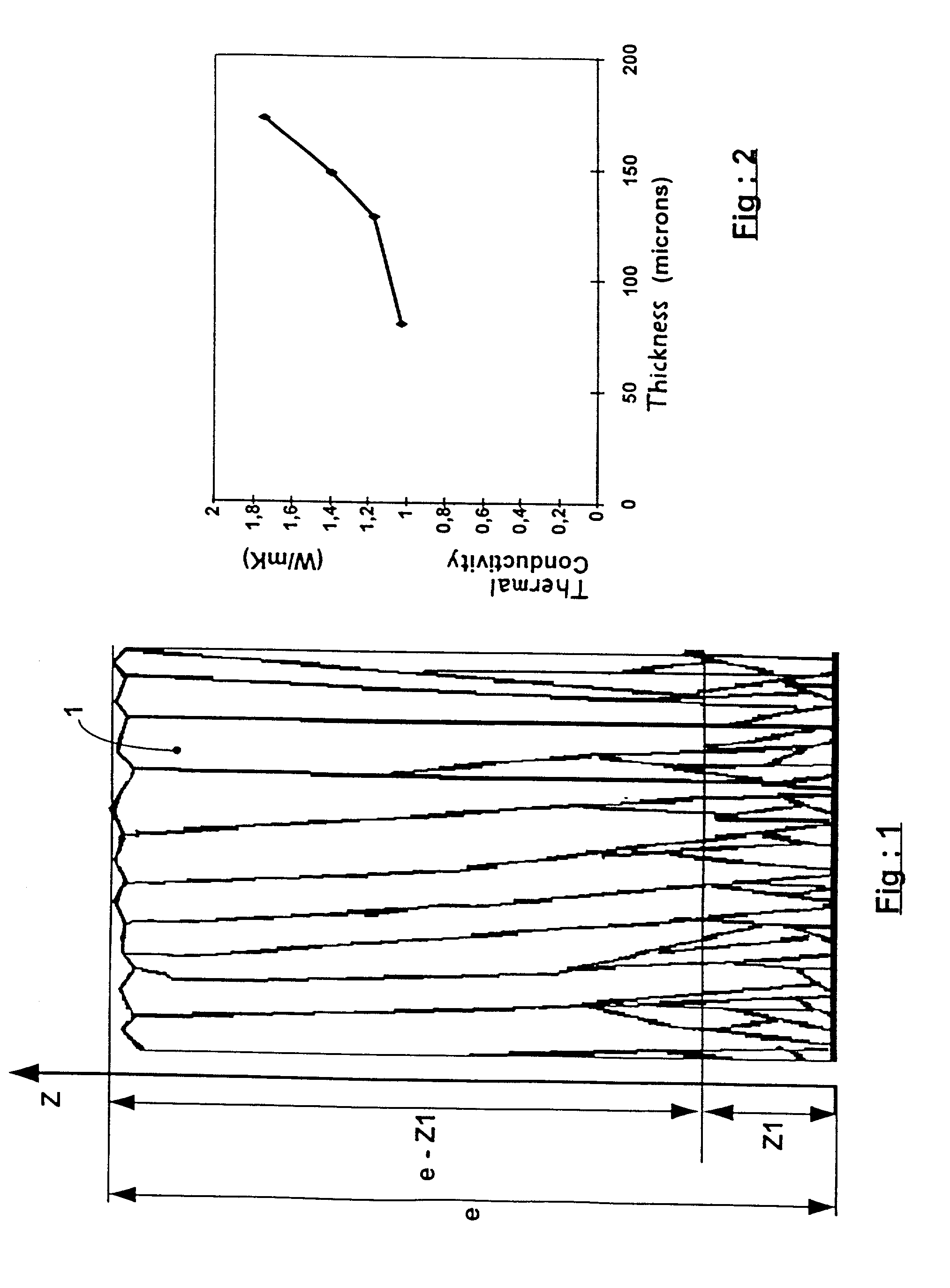
[0012] EB-PVD ceramic layers may have undeniable advantages for use on turbine blades, but they suffer from the major disadvantage of a thermal conductivity (typically from 1.4 to 1.9 W / mK) which is twice that of plasma sprayed heat barriers (from 0.5 to 0.9 W / mK). This difference in thermal conductivity is associated with the morphology of the deposits. The ceramic microcolumns perpendicular to the article surface which are found in EB-PVD depositions offer little hindrance to heat transfer by conduction and by radiation, whereas plasma sprayed depositions have a network of micro cracks which extend substantially parallel to the plane of the deposit, usually in the form of incomplete joints between the ceramic droplets which are crushed in the spraying. These micro cracks are much more effective in preventing heat conduction through the deposit. The insulation provided by a ceramic layer is proportional to its conductivity and thickness. For a given insulation level, halving the thermal conductivity of the ceramic layer would enable the coating thickness to be approximately halved--a considerable advantage when used on rotor blades subjected to centrifugal force.

Problems solved by technology

However, this approach is limited by the ability of the turbine components, such as the diffusers and moving blades of the high pressures stages, to withstand high temperatures.
However, the application of a ceramic coating to a metal article poses the problem of differential expansion of the metal and the ceramic during thermal cycling.
Also, electron guns require pressures of less than 10.sup.-4 Torr if they are to operate (arcing problems) which means that the electron gun must be pumped separately from the pumping of the chamber.
Some of the oxygen thus dissociated from the zirconium oxide molecules is lost as a result of the pumping of the chamber, with the consequence that the zirconia deposits are rendered substoichiometric (oxygen depleted).
EB-PVD ceramic layers may have undeniable advantages for use on turbine blades, but they suffer from the major disadvantage of a thermal conductivity (typically from 1.4 to 1.9 W / mK) which is twice that of plasma sprayed heat barriers (from 0.5 to 0.9 W / mK).
However, a sandwich structure of this kind consisting of nanometric layers suffers from thermal instability.
However, a layer of this kind is not suitable for retaining a low thermal conductivity since heat ageing leads of course to densification of the columns and reduces the density spread between the various layers.
Also, the association of a high voltage with the high temperatures (1000.degree.C.) required for EB-PVD deposition greatly complicates industrial implementation of the method.
As a rule, heat barriers having a laminated microcomposite structure (more commonly called a multilayer structure)--i.e., a microstructure based on the presence of interfaces to increase the resistance to heat flow--are unsuitable for high-temperature use because of the instability of the interfaces in operation.

Method used


Image

  • Ceramic heat barrier coating having low thermal conductivity, and process for the deposition of said coating
  • Ceramic heat barrier coating having low thermal conductivity, and process for the deposition of said coating
  • Ceramic heat barrier coating having low thermal conductivity, and process for the deposition of said coating

Examples


Embodiment Construction

[0031] The invention is based on a finding that a vapour phase deposited ceramic coating has a morphology 1 which changes over its thickness such as shown in FIG. 1. This morphology gradient is marked in particular by a density of mircocolumns 1 which decreases as a function of deposit thickness. The microcolumns are very fine at the interface with the substrate and can be likened to fibres, but tend to flare out in the outer region of the ceramic layer. One of the consequences of the change in the morphology of the ceramic coating with its thickness is that the thermal conductivity of the coating increases with its thickness (see FIG. 2). The outer region of the ceramic coating has a thermal conductivity which is higher than the coating region adjacent the substrate. This effect has been noticed in the case of materials which are very good heat conductors, such as diamond deposited by CVD, and in the case of poorer conductors such as yttriated zirconia. The morphology of a vapour p...


PUM

PropertyMeasurementUnit
diameteraaaaaaaaaa
thicknessaaaaaaaaaa
thicknessaaaaaaaaaa

Abstract

A ceramic heat barrier coating is deposited on a substrate so that the coating has a columnar growth pattern which is interrupted and repeated a number of times throughout its thickness by successive regermination of the ceramic deposit. The regermination is obtained by a vapour phase deposition process wherein a polluting gas is introduced intermittently during the deposition of the ceramic. The resulting ceramic coating has a lower thermal conductivity than conventional columnar ceramic coatings.

Description

[0001] 1. Field of the Invention[0002] The invention relates to a ceramic heat barrier coating having low thermal conductivity, a process for depositing such a ceramic coating, and to metal articles protected by the coating. The invention is particularly applicable to the protection of hot superalloy components of turbomachines, such as the turbine blades or diffusers.[0003] 2. Summary of the Prior Art[0004] The manufacturers of turboengines, whether for use on land or in aeronautics, face constant demands to increase engine efficiency and reduce fuel consumption. One way of addressing these demands is to increase the burnt gas temperature at the turbine inlet. However, this approach is limited by the ability of the turbine components, such as the diffusers and moving blades of the high pressures stages, to withstand high temperatures. Refractory metallic materials known as superalloys have been developed to make such components. These superalloys, which are nickel or cobalt or iron...

Claims


Application Information

Patent Timeline
Patent Type & Authority Applications(United States)
IPC IPC(8): B32B15/04B32B18/00F02C7/00C23C4/10C23C14/00C23C14/08C23C14/54C23C16/00C23C28/04F01D5/28F01D9/02
CPCC23C14/083C23C14/30C23C28/04C23C28/3215C23C28/345C23C28/3455Y10T428/12611Y10T428/24942Y10T428/12618Y10T428/12549Y10T428/24926Y10T428/1259
Inventor JASLIER, YANN PHILIPPEMALIE, ANDRE HUBERT LOUISHUCHIN, JEAN-PIERRE JULIEN CHARLESALPERINE, SERGE ALEXANDREPORTAL, ROMAIN
Owner SN DETUDE & DE CONSTR DE MOTEURS DAVIATION S N E C M A
Why Eureka
Try Eureka