Alloy flake for rare earth magnet, production method thereof, alloy powder for rare earth intered magnet, rare earth sintered magnet, alloy powder for bonded magnet and bonded magnet

Active Publication Date: 2005-02-10
TDK CORPARATION
View PDF15 Cites 55 Cited by
  • Summary
  • Abstract
  • Description
  • Claims
  • Application Information

AI Technical Summary

Benefits of technology

[0034] In view of the foregoing, an object of the first aspect of the present invention is to provide a main phase alloy for a rare earth magnet, the alloy being formed of an R-T-B alloy and to be subjected to the two-alloy blending method, wherein anisotropic magnetic field is enhanc

Problems solved by technology

Specifically, when the alloy ingot is produced through mold casting, a slow cooling rate of the cast ingot often results in formation of large crystal grains in the R2T14B phase, and R-rich phase forms large aggregates which are locally present in the ingot.
Therefore, particles formed only of the main phase (R2T14B phase) containing no R-rich phase and particles formed only of the R-rich phase are produced, whereby homogeneously mixing the main phase and R-rich phase becomes difficult.
Another problem involved in mold casting is that γ-Fe tends to be formed as primary crystals, due to the slow cooling rate.
If α-Fe remains even after sintering, magnetic characteristics of the sintered product are deteriorated.
However, in the center portion of the alloy ingot where solidification is finally complete, crystal grains have a large grain size and R-rich phase forms aggregates in some regions, because of a considerably slow solidification rate in the center portion.
However, since a conventional CC method (e.g., a method disclosed in U.S. Pat. No. 2,817,624) employs a comparatively high rate of feeding molten alloy, the substantial solidification rate becomes slower than that employed in the SC method.
Such high chemical activity causes problematic oxidation during production of magnets or in the produced magnets.
As compared with the single-alloy method, the two-alloy blending method, which is widely em

Method used


Image

  • Alloy flake for rare earth magnet, production method thereof, alloy powder for rare earth intered magnet, rare earth sintered magnet, alloy powder for bonded magnet and bonded magnet
  • Alloy flake for rare earth magnet, production method thereof, alloy powder for rare earth intered magnet, rare earth sintered magnet, alloy powder for bonded magnet and bonded magnet
  • Alloy flake for rare earth magnet, production method thereof, alloy powder for rare earth intered magnet, rare earth sintered magnet, alloy powder for bonded magnet and bonded magnet

Examples


Example

Example 11

[0153] Neodymium, praseodymium, ferroboron, aluminum, and iron were mixed to thereby obtain the following alloy composition: TRE: 28.5% by mass (Nd: Pr=1:1 (in R)); B: 1.00% by mass; Al: 0.30% by mass; and a balance of iron. The resulting mixture was melted in an alumina crucible in an argon gas atmosphere (1 atm) by use of a high-frequency induction melting furnace. The resulting molten alloy was cast through strip casting, to thereby prepare alloy flakes.

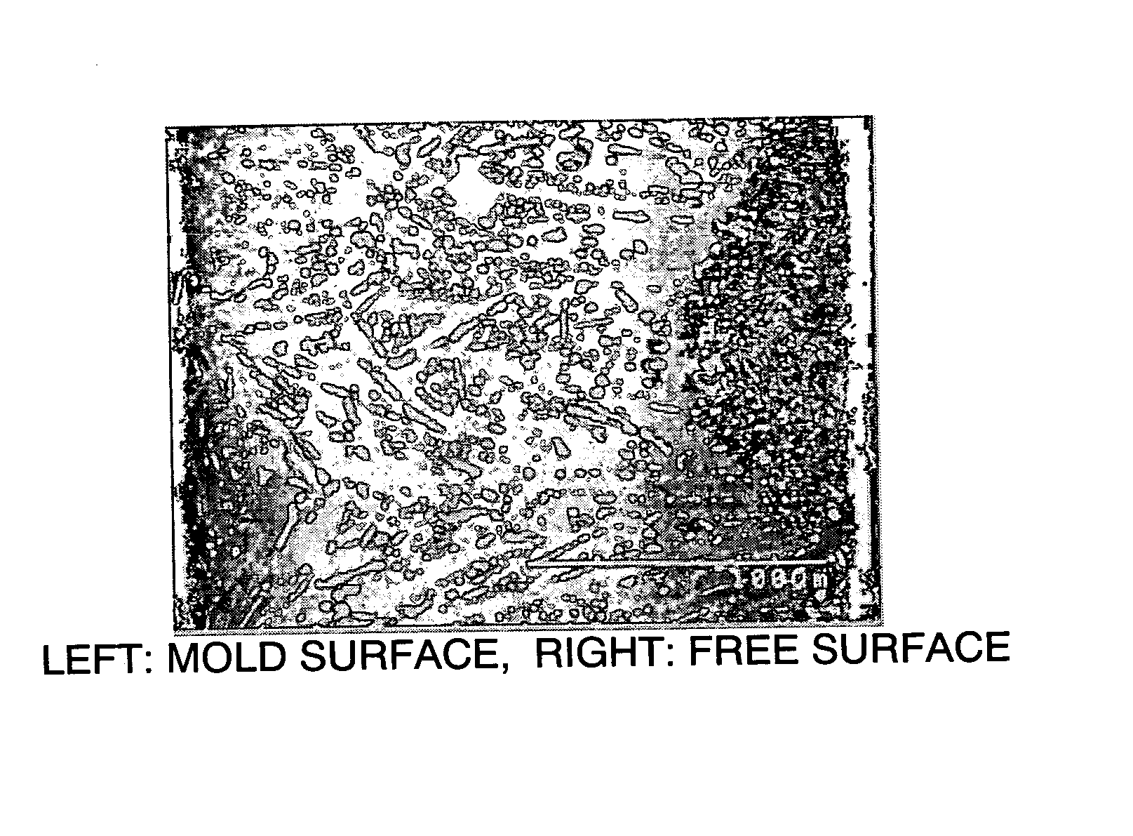
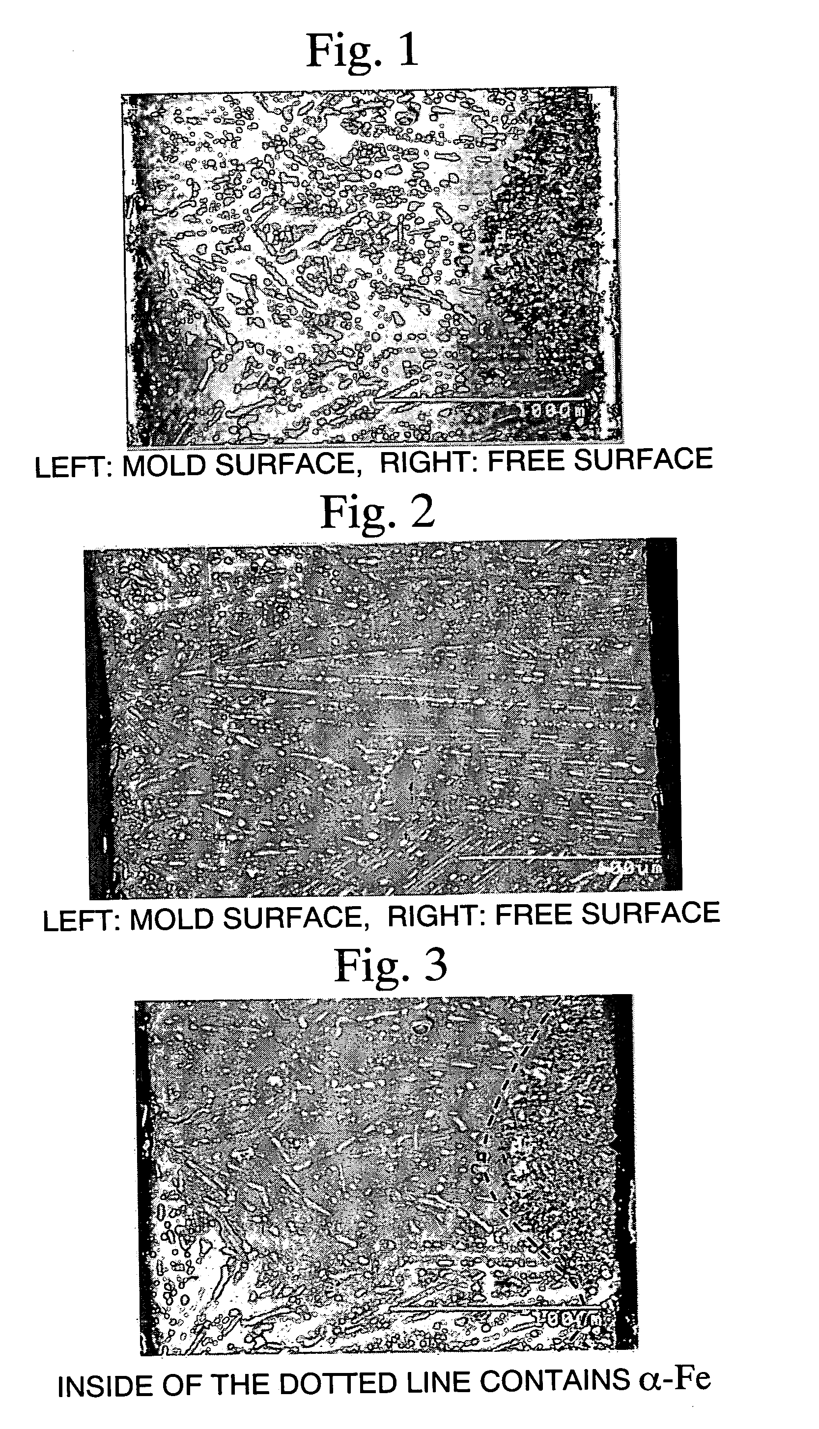
[0154] The roller for casting having a diameter of 300 mm and made of pure copper was employed. During casting, the inside of the copper roller was cooled by water. The roller had a cast surface roughness, as represented by 10-point average roughness (Rz), of 20 μm and was rotated at a peripheral velocity of 0.9 m / s, to thereby produce alloy flakes having a mean thickness of 0.26 mm.

[0155] The thus-produced alloy flakes were found to have a surface (mold side) roughness, as represented by 10-point average roughness (R...

Example

Example 12

[0156] An alloy having a composition similar to that of the alloy of Example 11 was melted in an alumina crucible in an argon gas atmosphere by use of a high-frequency induction melting furnace. The resulting molten alloy was cast by use of a centrifugal casting apparatus including a rotatable tundish.

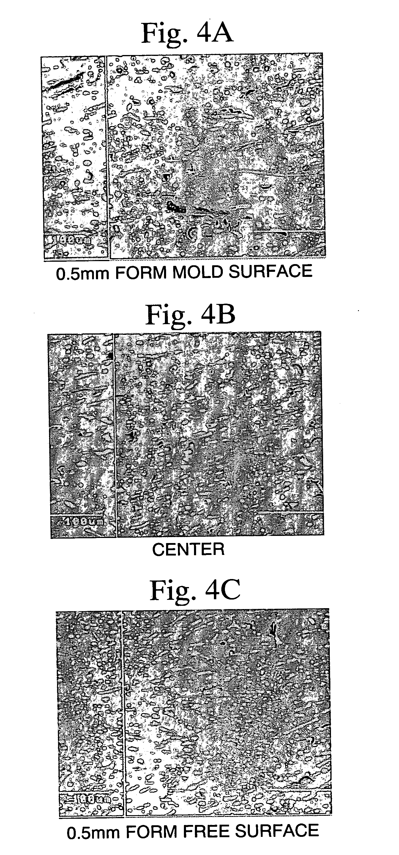
[0157] During casting, the molten alloy was deposited on the inner wall of the mold at an average deposition rate of 0.01 cm / s. The rotation rate of the mold was modified such that centrifugal force is adjusted to 3 G. Centrifugal force (about 20 G) was applied to the molten alloy contained in the rotatable tundish, to thereby sprinkle the molten alloy.

[0158] The thus-produced alloy flakes were found to have a thickness of 7 to 10 mm. From each alloy flake, each sample cut at levels in the thickness direction of 7 mm, 8.5 mm, and 10 mm was polished in a fixed state. Each flake was observed under a scanning electron microscope (SEM) and a back-scattered electron image (BEI)...

Example

Comparative Example 11

[0159] The procedure of Example 11 including preparing a raw material and melt-casting was repeated, except that a roller for casting having a surface roughness, as represented by 10-point average roughness (Rz), of 3.0 μm was employed.

[0160] The thus-produced alloy flakes were evaluated in a manner similar to that of Example 11. The alloy flakes were found to have a surface (mold side) roughness, as represented by 10-point average roughness (Rz), of 3.4 μm and to have a percent volume of α-Fe-containing region of 8%.

[0161] Working examples of production of rare earth magnets will next be described.


PUM

PropertyMeasurementUnit
Lengthaaaaaaaaaa
Lengthaaaaaaaaaa
Lengthaaaaaaaaaa

Abstract

Disclosed is a rare earth magnet in the R-T-B (rare earth element-transition metal-boron) system that is made from an improved composition and properties of main phase alloy in the R-T-B system containing Pr and a boundary alloy. Disclosed also is a manufacturing method of the rare earth magnet alloy flake by a strip casting method with improved rotating rollers such that the alloy flake has a specified fine surface roughness and has a small and regulated amount of fine R-rich phase regions. Consequently, the alloy flake for the rare earth magnet does not containing α-Fe and has a homogeneous morphology so that the rare earth magnet formed by sintering or bonding the alloy flakes exhibits excellent magnetic properties.

Description

CROSS-REFERENCE TO RELATED APPLICATION [0001] This application claims the benefit pursuant to 35 U.S.C. §119 (e) (1) of U.S. Provisional Applications, No. 60 / 343,187 filed on Dec. 31, 2001, U.S. Provisional Application No. 60 / 343,192 filed on Dec. 31, 2001, U.S. Provisional application No. 60 / 410,802 filed on Sep. 16, 2002, and a U.S. Provisional Application No. 60 / 430,649 filed on Dec. 4, 2002.TECHNICAL FIELD [0002] The present invention relates to a main phase alloy containing Pr and a boundary phase alloy for producing a rare earth magnet, to a method for producing the alloy, to a mixed powder for a rare earth sintered magnet, for a rare earth magnet; and to a rare earth magnet. The present invention also relates to rare earth magnet alloy flake, formed of an R-T-B alloy (R represents at least one rare earth element including Y; T represents transition metals including Fe as an essential element; and B represents boron); a method for producing the flake; to a rare earth sintered ...

Claims


Application Information

Patent Timeline
IPC IPC(8): B22F1/06B22F1/068B22F9/02B22F9/10C22C1/04C22C38/00C22C38/10H01F1/057
CPCB22F1/0007H01F41/0293B22F9/023B22F9/10B22F2009/044B22F2009/045B22F2998/00B22F2998/10C22C1/0441C22C38/002C22C38/005C22C38/10H01F1/057H01F1/0571H01F1/0573H01F1/0577H01F1/0578B22F1/0055B22F1/0003B22D11/0622B22F9/04B22F1/068B22F1/06B22F1/09
Inventor SASAKI, SHIRO
Owner TDK CORPARATION
Why Eureka
Try Eureka