
Nanotube coatings for implantable electrodes

Active Publication Date: 2005-04-07
WILSON GREATBATCH LTD
View PDF42 Cites 34 Cited by
  • Summary
  • Abstract
  • Description
  • Claims
  • Application Information

AI Technical Summary

Benefits of technology

[0009] The resulting electrode is both biocompatible and biostable because the nanotube coating is covalently bonded to the electrode surface. Advantageously, the electrode exhibits relatively low polarization because of the greatly increased surface area imparted by the nanotubes. In that respect, the nanotube coating mimics the physical structure of the conventional sputter coated columnar titanium nitride. However, the excellent biocompatibility of nanotube coatings advantageously lessens or eliminates the requirement for a means of providing steroidal medication to the tissue surrounding the electrode.

Problems solved by technology

The disadvantage of titanium nitride, however, is that it degrades the electrical properties of surrounding tissue after implantation.
This, in turn, impacts the battery life of the system so that the medical device must be explanted sooner than desired.
The encapsulation process also interferes with sensing of intrinsic milivolt signals required by pacemakers.
However, eluting a steroidal medication to the implant site is not completely effective in eliminating the stimulation threshold rise due to encapsulation.
Steroidal medication eluting arrangements have a short duration of effectiveness, and also add cost and complexity to the system, add the risk of infection, and, in many cases, a portion of the electrode working surface must be dedicated to the medication administering function.
These designs meet the requirement of improved biocompatibility, but they do not have the high specific surface characteristics of columnar titanium nitride, and so fall short in polarization and sensing properties.

Method used


Image

  • Nanotube coatings for implantable electrodes
  • Nanotube coatings for implantable electrodes
  • Nanotube coatings for implantable electrodes

Examples


example i

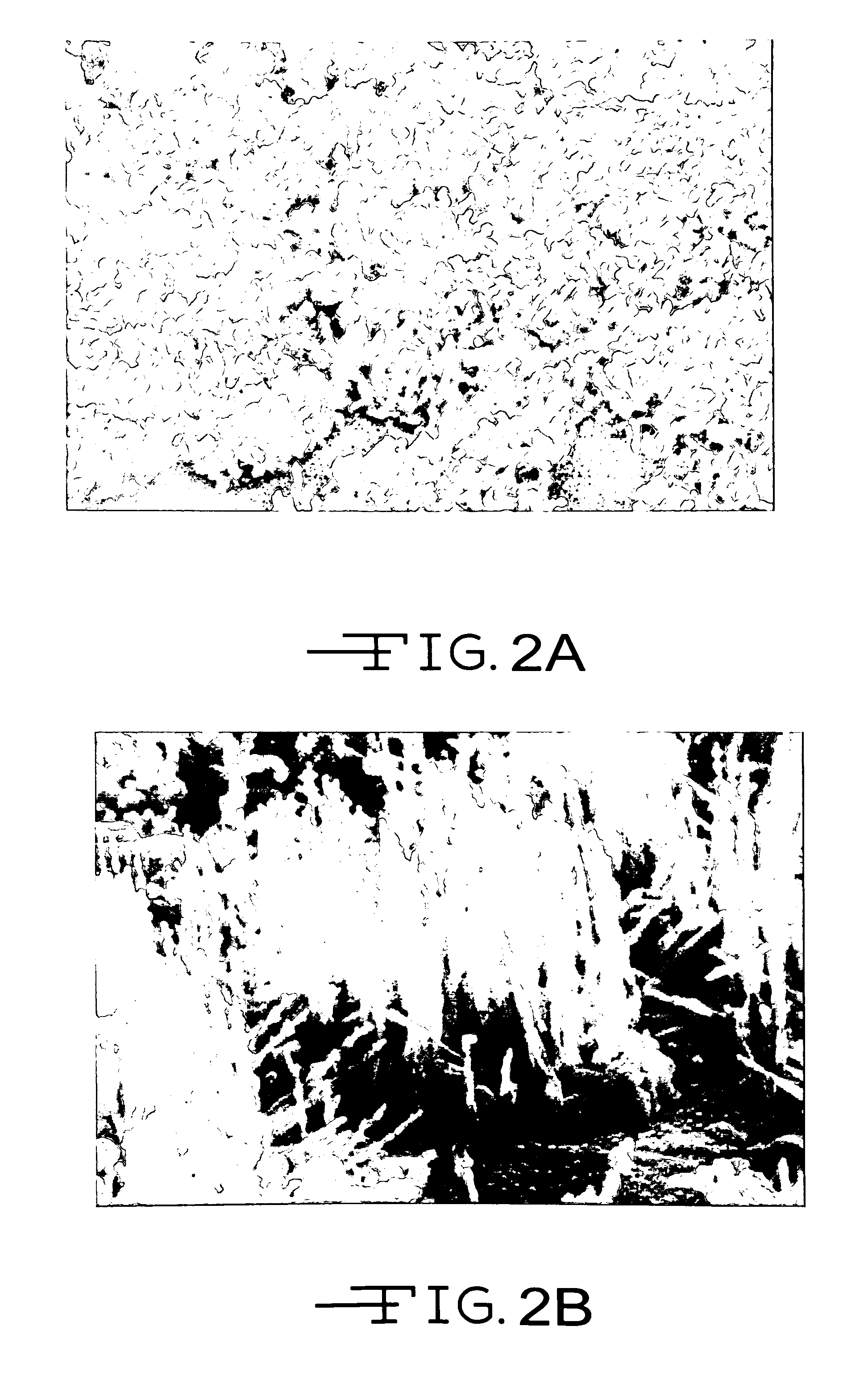
[0024] A tantalum substrate was placed in a closed chamber. The chamber was heated to about 650° C. with hydrogen gas flowing through the chamber at a rate of about 1 liter / min. for about every 20 cc of reactive volume. When the reaction chamber reached the desired temperature, 0.5 liter / min of acetylene was added to the reaction gas stream. After about 15 minutes, it was observed that a useable nanotube coating had grown in-situ on the tantalum substrate. The photographs in FIGS. 3A and 3B show the resulting in-situ grown nanotube coating on the tantalum substrate at magnifications of 20,000× and 50,000×, respectively.

[0025] A useable nanotube coating can be grown in a similar manner on a substrate of titanium, zirconium, iridium, platinum, niobium, and nitrogen-doped amorphous carbon, or virtually any substrate provided with a thin film coating of these materials. These catalytic or nucleating materials have biocompatible properties similar to those of tantalum.

example ii

[0026] Etching in aqueous oxalic acid solution at 80° C. for 1 hour cleaned a titanium electrode tip.

[0027] A chloroiridic acid solution was prepared by dissolving 1 gram of chloroiridic acid in 35 ml of isopropyl alcohol at room temperature with stirring. Loose nanotube powder was then added while stirring at a high shear rate until a thick, viscous mixture was obtained. The iridium oxide coated substrate was then dipped into the mixture to provide a viscous coating of nanotubes thereon. Heating the coated substrate to about 340° C. in air for about 1 hour converted the metal chloride to iridium metal, which was then subsequently oxidized by further heating. The iridium oxide coated substrate had embedded nanotubes.

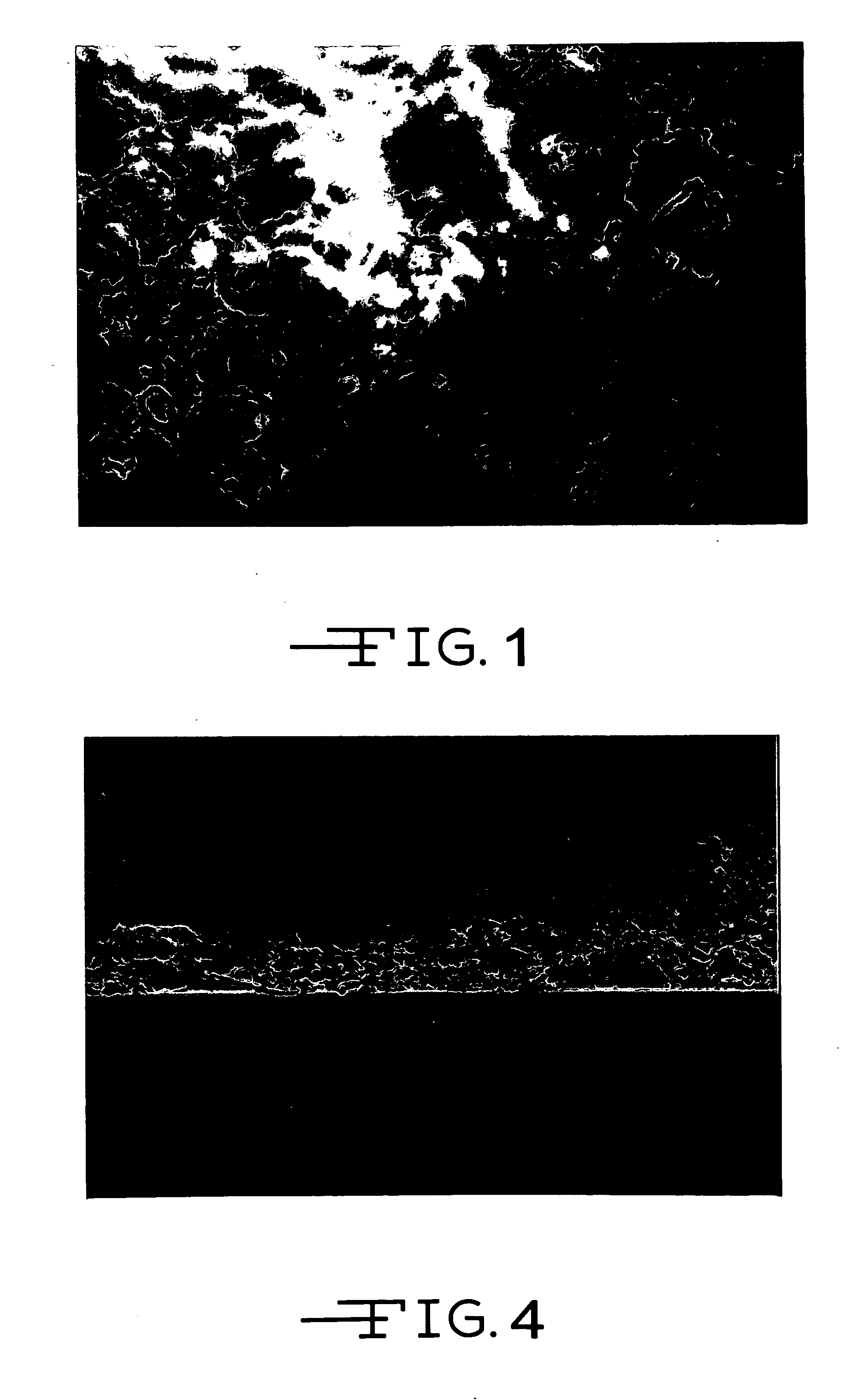
[0028] The photograph in FIG. 4 shows a similarly generated nanotube coating bonded to a PYREX® glass substrate with iridium oxide binder at a magnification of 20,000×. While the experiment was done with a titanium electrode tip, the reason for the glass substrate was ...


PUM

PropertyMeasurementUnit
Temperatureaaaaaaaaaa

Abstract

Coatings for implantable electrodes consisting of single- or multi-walled nanotubes, nanotube ropes, carbon whiskers, and a combination of these are described. The nanotubes can be carbon or other conductive nanotube-forming materials such as a carbon-doped boron nitride. The nanotube coatings are grown “in situ” on a catalytic substrate surface from thermal decomposition, or they are bonded to the substrate using a metal or conductive metal oxide thin film binder deposited by means of a metal compound precursor in liquid form. In the latter case, the precursor / nanotube coating is then converted to a pure metal or conductive metal oxide, resulting in the desired surface coating with imbedded nanotubes.

Description

CROSS-REFERENCE TO RELATED APPLICATION [0001] The present application claims priority from U.S. provisional application Ser. No. 60 / 429,471, filed Nov. 26, 2002.BACKGROUND OF THE INVENTION [0002] 1. Field of the Invention [0003] This invention generally relates to coatings for implantable electrodes such as pacing electrodes, neurostimulator electrodes, and electroporating electrodes and sensing electrodes. The three overriding requirements for these types of electrodes are biocompatibility, biostability, and low energy loss. Broadly, the biocompatibility requirement is met if contact of the electrode with body tissue and blood results in little or no immune response from the body, especially thrombogenicity (clotting) and encapsulation of the electrode with fibrotic tissue. The biostability requirement means that all physical, electrical, and chemical properties of the electrode / coating system remain constant and unchanged over the life of the patient. The low energy loss requireme...

Claims


Application Information

Patent Timeline
IPC IPC(8): A61B5/296A61L31/00A61N1/05A61N1/08A61N1/34B21C37/00
CPCA61N1/05A61N1/0551A61N1/056A61N1/36017A61N1/3605B21C37/00B82Y30/00A61N1/08
Inventor O'BRIEN, ROBERT C.FRYSZ, CHRISTINE
Owner WILSON GREATBATCH LTD
Learn More