Biosensors and methods for their use

a biosensor and sensor technology, applied in the field of biosensors, can solve the problems of reducing the sensitivity of the sensor, and reducing the choice of post-fabrication (chip bonding) materials, so as to reduce the size of the sensor surface to volume ratio, reduce the size of the sensor, and improve the sensitivity. the effect of the sensitivity

Inactive Publication Date: 2005-04-28
RGT UNIV OF CALIFORNIA
View PDF7 Cites 48 Cited by
  • Summary
  • Abstract
  • Description
  • Claims
  • Application Information

AI Technical Summary

Benefits of technology

[0019] The methods and devices disclosed herein have a number of embodiments which provide innovative approaches to the detection of various macromolecules by, for example, separating the DNA hybridization/immunobiological binding process and the enzymatic reaction process for sensing into two locations by applying an electrophoretic separator. The excess enzymes and other unwanted molecules can be separated from the target molecules. Then, the target molecules can be electrically moved to an ISFET sensor for detection. By using this idea of separating the places where DNA hybridizes and enzyme activation/signal sensing occurs, the immobilization and washing steps become unnecessary. Without the washing step, one can eliminate the huge viscous dissipation occurring in small channel. The separator constitutes a large aspect ratio channel with tens or hundreds of nanometer in one dimension. This design leads to a large increase of the sensing surface to volume ...

Problems solved by technology

These are also time and power consuming steps.
In addition, the immobilized monolayer can be destroyed by a high temperature condition that limits the post fabrication (chip bonding) choices if a closed sensor is to be developed.
All of these issues, which come from these cumbersome steps, add complexities to the lab-on-chip design.
As noted above, th...

Method used


Image

  • Biosensors and methods for their use
  • Biosensors and methods for their use
  • Biosensors and methods for their use

Examples


example 1

Microchannels Integrated with Sidewall Mirrors for Biological Detection Using Molecular Beacon Technology

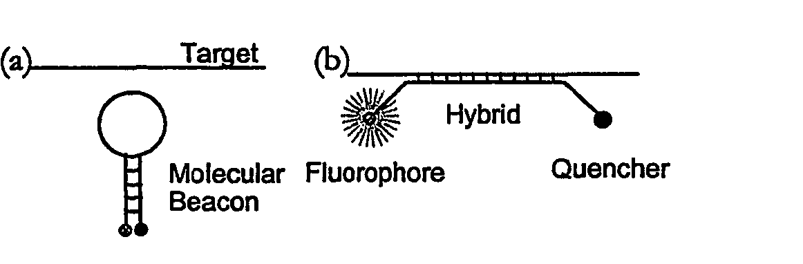
[0085] This illustrative example discloses the fabrication of microchannels integrated with sidewall mirrors and the application for in-channel optical DNA / RNA detection. The detection specificity is achieved by using molecular beacon CB) based DNA hybridization technique. Molecular beacons are highly sensitive and selective oligonucleotide probes (see e.g. S. Tyagi, F. R Kramer, “Molecular beacons: Probes that fluoresce upon hybridization”Nature Biotechnol. 14 (1996), 303-308) that become fluorescent upon hybridization with target DNA / RNA molecules as shown in FIG. 1. By using MB probe technology, two of the major but cumbersome steps of gene-based biosensors, probe immobilization and washing (see e.g. S. R. Mikkelsen, Electroanalysis, 8 (1996) 15; J. Gau, E. Lan, et al., Proceedings of the Fourth International Symposium on I-TAS (2000)), can be eliminated. This realizes in-cha...

example 2

Microchannels of Different Geometries Integrated with Sidewall Mirrors for Polynucleotide Detection Using Molecular Beacons

[0090] In this example, the eight hundred bases long nucleic acid targets used for detection were synthesized by polymerase chain reaction (PCR). The sense (5′-CAGAT GGGAT TAGCT AGTAG GTG-3′) (SEQ ID NO: 2) and antisense (5′-GTCTC ACGGT TCCCG AAGGC AC-3) (SEQ ID NO: 3) primers derived from the most conserved region of 16s rRNA of E. coli. (MC41000) were identical to those used in the previously reported study [See, e.g., T. H Wang et al., proceedings of METMBS'00, pp295-300]. Initially, 50 μl DNA solution with concentration of 0.2 μM and 50 μl MB solution of the same concentration were mixed for biosensor characterization. The signal to noise ratio (SNR) and detection limit of channels with various geometries and surface coatings are determined by testing the different channels with the serially diluted solution. Because of the introduction of molecular beacons...

example 3

Electrical Focusing for Laser Induced Fluorescence Based Single DNA Molecules Detection

[0095] This example describes a method, 3-D electrokinetic focusing technique, to concentrate fluorescence labeled molecules into a tiny probing volume to enhance the mass detection efficiency for laser induced fluorescence (LIF) based molecular sensing. By applying this method for detecting DNA of very low concentration (20 fM), single molecule fluorescence bursts were real time determined, and more than five times enhancement of mass detection efficiency was achieved. Comparing this method with the other molecular focusing techniques such as hydrodynamic focusing [A. Castro and J. G. K Williams, Anal. Chem. 69, 3915-3920 (1997)] and electric current focusing [S. C. Jacobson and J. M. Ramsey, Anal. Chem. 69, 3212-3217 (1997)]. This method can also enhance the concentration detection limit and overcome the off-center problems of sample stream due to the slight conductivity changes of the cross ch...


PUM

PropertyMeasurementUnit
Fractionaaaaaaaaaa
Fractionaaaaaaaaaa
Fractionaaaaaaaaaa

Abstract

The invention disclosed herein provides biosensors and methods which increase the sensitivity of assays of optically labelled molecules fluorescently tagged polypeptides and polynucleotides while decreasing the sample volume required for detection. By integrating reflective sidewalls into the receptacles used in such assays, the signal-to-noise ratio of the optical signal is increased significantly. Typically the receptacles are microchannels. In addition, the geometry of the receptacles can be controlled C to further optimize the signal-to-noise ratio of the optical signal. The invention disclosed herein further provides methods and devices involving integrated electronics, wherein an element such as a diode, a transistor, an integrated circuit etc., is integrated with a bioreactor/channel in order to facilitate the detection or fabrication of bio-materials.

Description

[0001] This application claims the benefit of U.S. provisional application No. 60 / 225,077, filed Aug. 14, 2000, the entire contents of which are incorporated herein by reference.[0002] This invention was made with Government support under Grant No. N66001-96-C-83632 awarded by the Navy. The Government has certain rights in this invention.FIELD OF THE INVENTION [0003] The invention described herein relates to biosensors for the detection of biological molecules such as polynucleotides. The invention further relates to methods and devices involving integrated electronics, wherein an element such as a diode, a transistor, an integrated circuit etc., is integrated with a bio-reactor / channel in order to facilitate the detection and / or fabrication of bio-materials. BACKGROUND OF THE INVENTION [0004] Biosensors are sensors that detect chemical species with high selectivity on the basis of molecular recognition rather than the physical properties of analytes. See, e.g., Advances in Biosenso...

Claims


Application Information

Patent Timeline
IPC IPC(8): B01L3/00C12M1/34C12Q1/68C12Q1/6825C40B60/14G01N21/03G01N21/05G01N21/64G01N33/53
CPCB01J2219/00317G01N2021/0346B01J2219/00576B01J2219/00605B01J2219/00653B01J2219/00666B01J2219/00702B01L3/5027B01L3/502707B01L2300/168C12Q1/6825C40B60/14G01N21/0303G01N21/05G01N21/6428G01N21/645G01N27/4145G01N27/447G01N2021/058G01N2021/6463G01N2021/6476G01N2021/6482B01J2219/00511
Inventor HO, CHIH-MINGWANG, TZA-HUEI
Owner RGT UNIV OF CALIFORNIA
Why Eureka
Try Eureka