Method of preparing membrane electrode assemblies with aerogel supported catalyst

a technology of catalyst and catalyst layer, which is applied in the direction of cell components, final product manufacturing, sustainable manufacturing/processing, etc., can solve the problems of unfavorable use of catalyst, and unpredictable variation in thickness of polymer electrolyte in the catalyst layer, so as to achieve superior performance over measly, the effect of modifying the porosity of the aerogel and pore size of the aerogel

Inactive Publication Date: 2005-09-15
HARA HIROAKI S +1
View PDF6 Cites 25 Cited by
  • Summary
  • Abstract
  • Description
  • Claims
  • Application Information

AI Technical Summary

Benefits of technology

[0013] One advantage to the above-described invention is derived from the use of aerogels themselves. Aerogel materials possess a wide variety of exceptional properties that allow for their chemical synthesis to be controlled. In particular, it should be noted that while the pore sizes of common carbons used as supports for PEMFC catalysts cannot be altered, the pore sizes of aerogels can be altered. The porosity can also be manipulated to produce a desired structure. Furthermore, the porosity of the aerogel can be modified via chemical synthesis with further distribution of metallic particles to optimize the contact of the aerogel with an ion conducting polymer electrolyte.
[0014] Another advantage is that manufacture of membrane electrode assemblies (MEAs) by the above-described method provides superior performance over MEAs produced by other methods. The superior performance provided by the method may be due in part to a marked increase in adsorption

Problems solved by technology

This agglomeration often contributes to subsequent sintering of the metal during operation of the fuel cell, uneven distribution of the polymer electrolyte relative to the carbon spheres of the catalyst metal particles, and permeability of the reactants at the three-phase boundary.
On the microscale level, this means that the distribution of polymer electrolyte in the catalyst layer has an unpredictable variation in thickness around and between the supported metal particles.
A further redistribution of phases could occur further with time due to the difference in electrochemical potentials and local currents, which could result in the internal delamination of the polymer from the sur

Method used


Image

  • Method of preparing membrane electrode assemblies with aerogel supported catalyst
  • Method of preparing membrane electrode assemblies with aerogel supported catalyst
  • Method of preparing membrane electrode assemblies with aerogel supported catalyst

Examples


example 1

Characterization of Aerogel Supported Platinum Catalysts

[0057] Aerogel supported platinum catalysts have been provided for subsequent use in the manufacture of cathode catalyst layers for fuel cell applications. Two catalysts that differ in platinum content and porosity were analyzed. The results of each catalyst are presented below in Table 1.

TABLE 1Physical characteristics of catalyst samplesSamplePlatinum content (%)Porosity (nm)1371622022

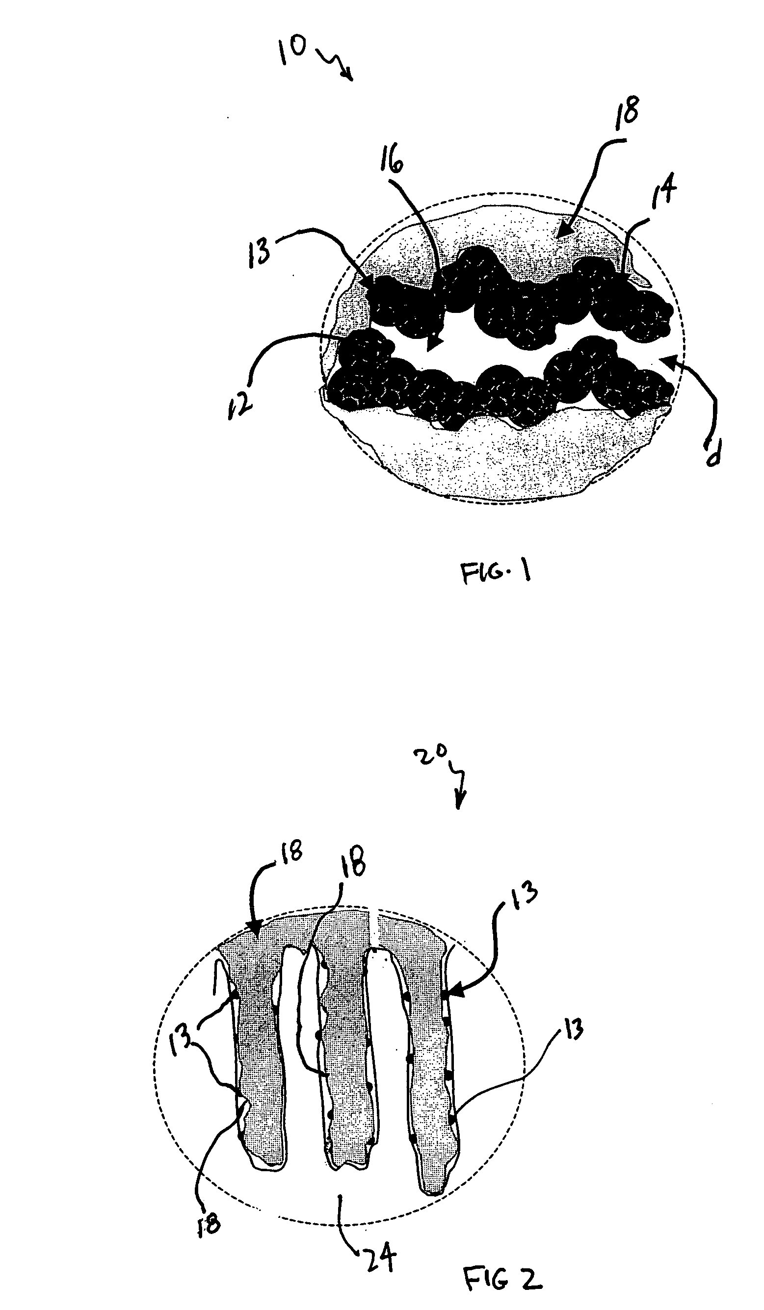
[0058] The porosity was estimated using the Brunauer-Emmett-Teller (BET) method. In the BET method, adsorption and desorption isotherms of nitrogen were measured using a gas adsorption analyzer (Sorptomatic 1990, available from Horiba). Mesopore size distributions and mesopore volumes were estimated for pore diameters of 2 nm to 50 nm by applying the Dollimore-Heal method to the desorption isotherm of nitrogen.

[0059] The mean diameter and the surface area of the platinum particles were measured by hydrogen adsorption. High resolution transmi...

example 2

Preparation of Catalyst Paste and MEA

[0061] For anodes (reference electrodes), porous carbon aerogel supported catalysts from Tanaka Kikinzoku Kogyo (TKK) having metal contents of about 53.5% metal were mixed in nitrogen atmospheres with water, 5 wt. % Nafion® solutions, and appropriate solvents. The prepared mixtures were homogenized using an Ultra-Terrux homogenizer with further evaporation of the excess amount of the solvent to obtain the appropriate viscosity.

[0062] Cathode aerogel supported catalysts having different platinum loadings and pore size distributions received as rods from Aerogel Composite, LLC, were ground in an agate mortar and subsequently prepared as inks by the above-mentioned process.

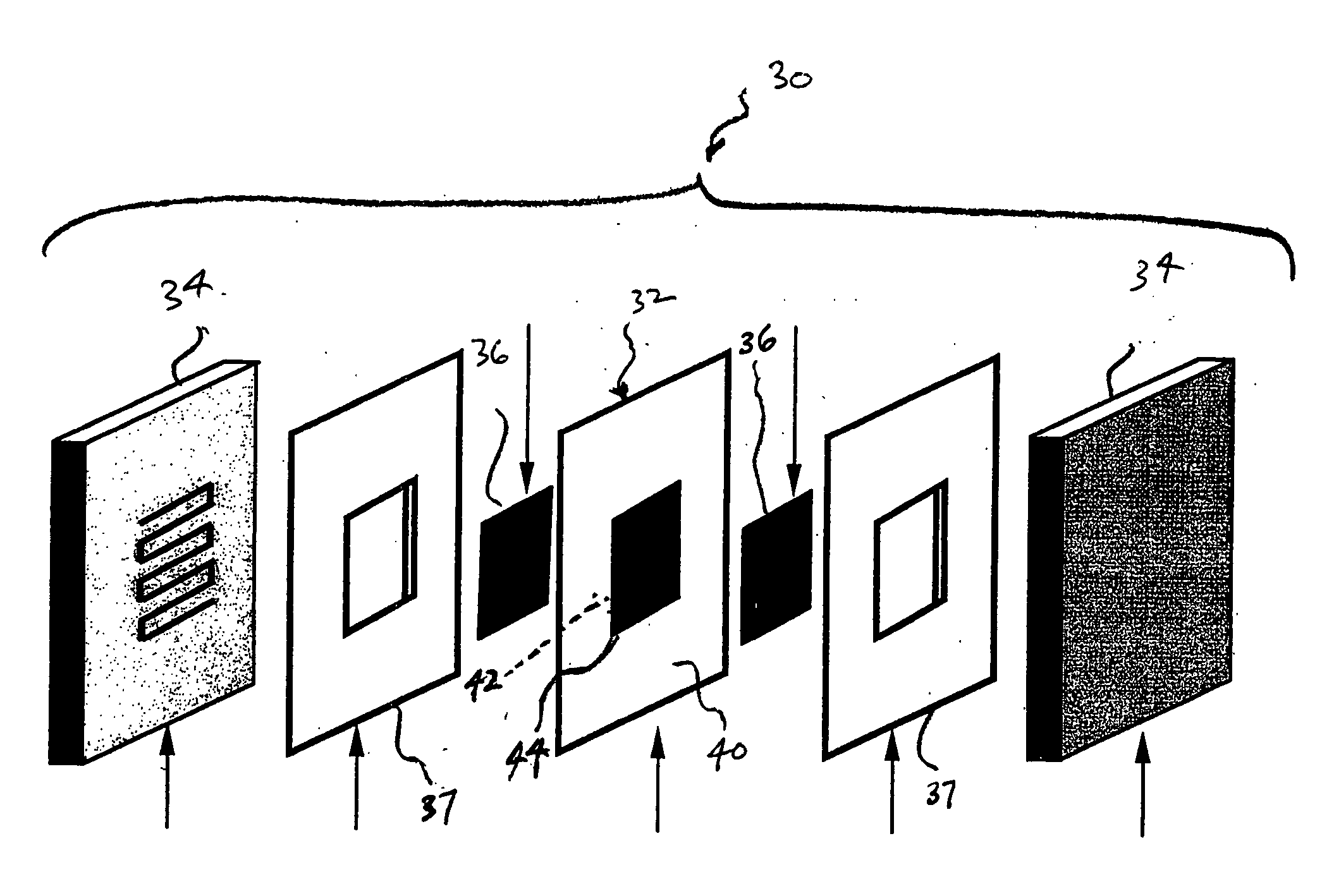
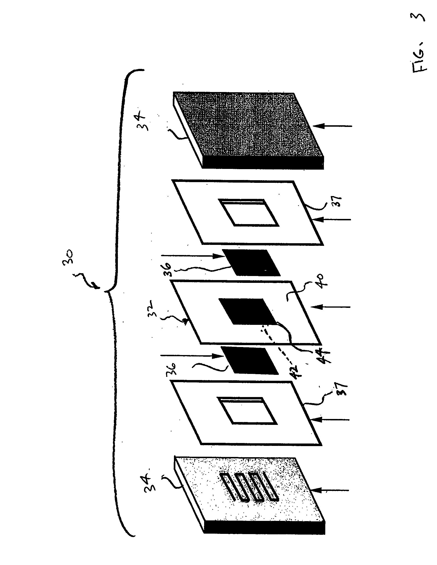
[0063] Polytetrafluoroethylene film, which is available as Teflon® from E. I. duPont de Nemours and Company, Wilmington, Del., was used as decals for the application of the anodes and cathode. The films were weighed before the application of the catalyst inks. The inks were the...

example 3

Measurement of Platinum Particle Surface Area

[0066] The measurements of platinum surface area in contact with the perfluorosulfonated ionomer surface area and thus available for electrochemical reaction were made using a cyclic voltammetry (CV) technique in a four-point probe configuration. The use of cyclic voltammetry was used to determine the amount of hydrogen crossing over the membrane that was oxidized. Cyclic voltammetry plots were obtained in the range of 0.01 to 0.8 volts (V) at a scan rate of 20 millivolts per second (mV / sec) at room temperature (about 23 degrees C. to about 27 degrees C.) using a potentiostat (Princeton potentiostat Model 273). To avoid the presence of oxygen, pure nitrogen was supplied to the cathode side (the working electrode) of an MEA and pure hydrogen was supplied to the anode side (the counter electrode) of the MEA at a flow rate of 200 cubic centimeters per minute (cc / min).

[0067] An estimation of the electrochemical surface area (ESA) of the cat...


PUM

PropertyMeasurementUnit
Temperatureaaaaaaaaaa
Compositionaaaaaaaaaa
Chemically inertaaaaaaaaaa

Abstract

A process of manufacturing a membrane electrode assembly comprises the steps of preparing an electrode-forming catalyst ink comprising porous aerogel supported catalyst and an electrolyte; depositing the prepared catalyst ink on a polymer film to form one or more catalyst layers; hot-pressing the one or more catalyst layers deposited on the polymer film at a temperature that is higher than a glass transition temperature of the electrolyte; decreasing the temperature of the hot-pressed catalyst layer and the polymer film; and removing the polymer film from the one or more catalyst layers.

Description

TECHNICAL FIELD [0001] This invention relates generally to polymer electrolyte membrane fuel cells, and, more particularly, to a method of making electrodes with aerogel supported catalysts in combination with membrane electrode assemblies. BACKGROUND OF THE INVENTION [0002] Various types of fuel cells have been proposed for applications such as electrical vehicles, power plants, and the like. One type of fuel cell uses a polymer electrolyte membrane that has the ability to conduct hydrogen therethrough to provide for ion exchange. The ion exchange is effected between electrodes (an anode and a cathode) positioned on the membrane. The electrodes are formed of conductive materials such as carbon having metal particles deposited on the surface thereof. In the operation of the fuel cell, gas and / or liquid fuel (e.g., hydrogen, alcohol, and the like) is supplied to the anode, and an oxidant (e.g., oxygen or air) is supplied to the cathode. The ion exchange across the electrodes provides...

Claims


Application Information

Patent Timeline
IPC IPC(8): B29C41/02H01M4/88H01M4/92H01M8/10
CPCH01M4/8807H01M4/881H01M4/8828Y02E60/521H01M4/921H01M4/926H01M8/1004H01M4/8896Y02P70/50Y02E60/50
Inventor HARA, HIROAKI S.SMIRNOVA, ALEVTINA
Owner HARA HIROAKI S
Why Eureka
Try Eureka