Metal-air battery with ion-conducting inorganic glass electrolyte

a metal-air battery and inorganic glass technology, applied in the field of metal-air or metal-oxygen batteries, can solve the problems of metal anodes, na and li, and metal anodes suffer from severe corrosion problems

Inactive Publication Date: 2006-03-23
JANG BOR Z
View PDF9 Cites 135 Cited by
  • Summary
  • Abstract
  • Description
  • Claims
  • Application Information

AI Technical Summary

Benefits of technology

[0009] It is an object of the present invention to provide a metal-oxygen (metal-air) electrochemical cell or battery that features a safe and reliable solid-state electrolyte.

Problems solved by technology

In addition to the above oxygen-reducing reactions, there is also an undesirable, non-beneficial reaction of aluminum in both types of electrolyte to form hydrogen, as follows:
Despite the fact that metals such as Al, Mg, Ca, Na and Li have a much higher energy density than zinc, these five metal anodes (Al, Mg, Ca, Na and Li) suffer from severe corrosion problems.
In some cases, the presence of water in an aqueous electrolyte could create a safety concern due to potential violent reactions between Na and water or between Li and water.
The presence of oxygen tends to aggravate the corrosion problem.
It is a great pity that metals with high power or energy density like Al, Mg, Ca, Na and Li have not been extensively used in a primary or secondary cell.
However, the afore-mentioned problems have severely limited the wider implementation of metal-air batteries.
However, the organic or polymer electrolyte-based metal-air cell still suffers from some drawbacks.
This is an undesirable feature since solvents could potentially pose a health threat and are often difficult to handle properly in a real manufacturing environment.
This type of electrolyte, composed of a polymer host, an electrolyte salt and a solvent, cannot be easily prepared in an ultra-thin film form.
Further, a thin liquid solvent-based electrolyte layer is subject to solvent vaporization, resulting in a reduced ion conductivity.

Method used


Image

  • Metal-air battery with ion-conducting inorganic glass electrolyte
  • Metal-air battery with ion-conducting inorganic glass electrolyte
  • Metal-air battery with ion-conducting inorganic glass electrolyte

Examples


example 1

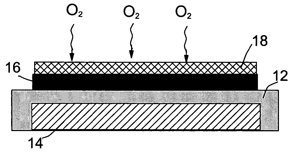
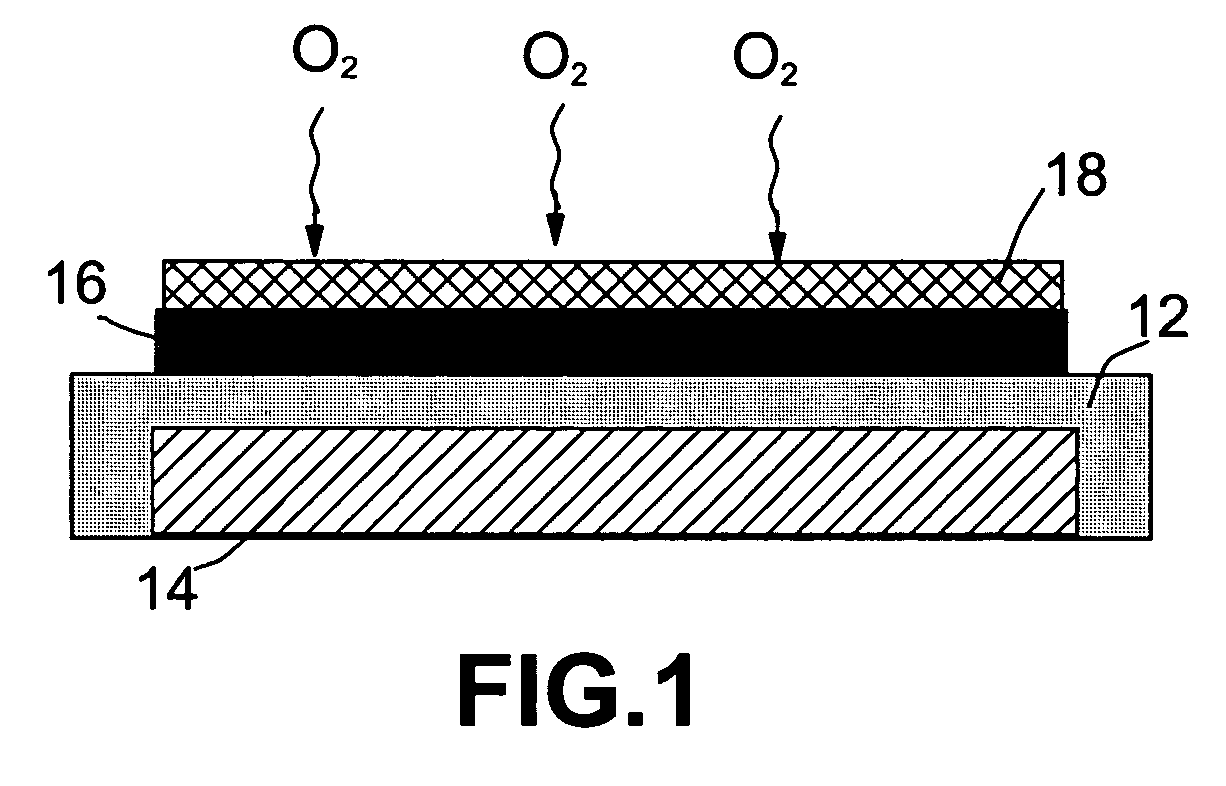
[0033] A plasma-assisted CVD was used to prepare silicon oxide (SiOx)—(LiOx)-based films on Li-coated glass substrate by introduction of an organosilicon compound into a plasma reactor. Liquid organosilicon, 1,1,3,3-tetra-methyl-disiloxane, was slightly heated to produce a vapor pressure of the siloxane sufficient to sustain a silicon flux to the plasma. A radio frequency-heated Li—Al rod was used to generate a stream of Li vapor into the plasma chamber essentially concurrently with siloxane vapor. A metering valve and a mass flow meter connected in series were used to control the flux of organosilicon. The lithium silicate deposition was continued until the thickness was approximately 2,000 Å.

[0034] The carbon air electrode was prepared by mixing a 10 wt. % PTFE emulsion (containing 0.05 to 0.5 μm PTFE particles in water) with carbon black. The mixture was stirred and ultrasonicated for 10 minutes and then dried in a vacuum at 80° C. The dried paste was milled to form a fine powde...

example 2

[0036] A lithium metal thin film having a thickness of 10 μm was formed on a copper foil having a size of 100 mm×50 mm and a thickness of 10 μm by vacuum evaporation and deposition. On the thin film of the lithium metal, a thin film of an inorganic glass electrolyte was formed to have a thickness of 1 μm. The glass electrolyte was selected from the following list (Table 1):

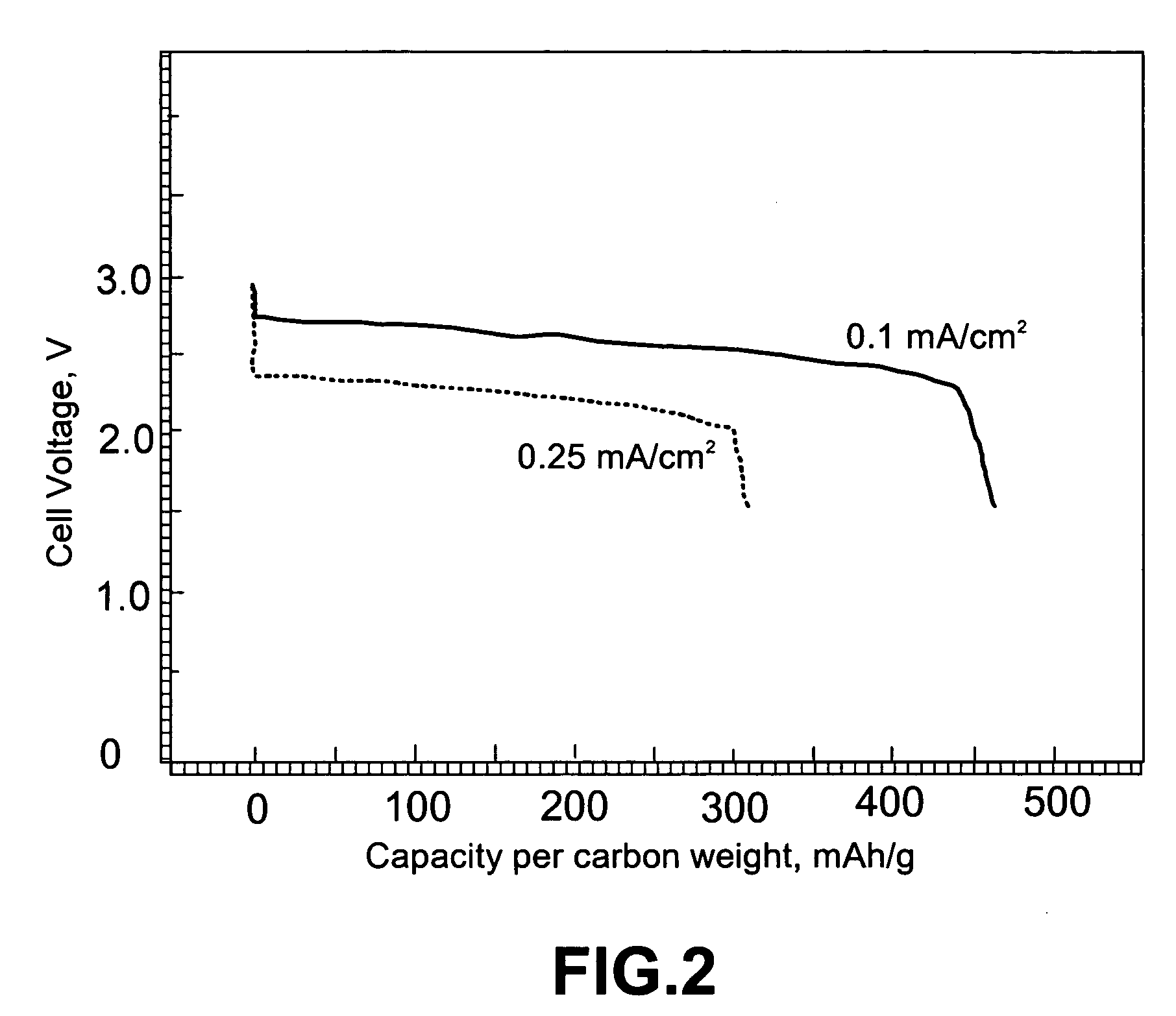
TABLE 1The ion conductivity, open circuit voltage (OCV), and dischargevoltage (at a current density of 0.1 mA / cm2) of selectedLi / oxygen batteries.Dis-IonicchargeSam-Chemical compositionconductivityOCVVoltagepleof glass electrolyteS / cmVoltsVolts2-a60Li2S—39.5SiS2—0.5Li3PO41.8 × 10−32.862.602-b57Li2S—38SiS2—5(Li2O—P2O5)2.0 × 10−32.792.52-c57Li2S—38SiS2—5(Li4SiO4)2.0 × 10−32.852.562-d57Li2S—38SiS2—5Li3BO31.8 × 10−32.862.52

[0037] The carbon-based oxygen electrode and the resulting Li / glass electrolyte / carbon cell package for Samples 2-a through 2-d were prepared according to the same procedures as in Example 1.

example 3

[0038] Samples 3-a, 3-b, 3-c, and 3-d were similar to Samples 2-a, 2-b, 2-c, and 2-d, respectively; but the glass electrolyte layer was approximately 10 μm instead of 1 μm. The discharge voltages of the Li / O2 batteries with thicker electrolyte layers appear to be smaller than those of their thinner counterparts (Table 2).

TABLE 2The ion conductivity, open circuit voltage (OCV), anddischarge voltage (at a current density of 0.1 mA / cm2) ofselected Li / oxygen batteries.Dis-IonicchargeSam-Chemical compositionconductivityOCVVoltagepleof glass electrolyte (10 μm thick)S / cmVoltsVolts2-a60Li2S—39.5SiS2—0.5Li3PO41.8 × 10−32.852.512-b57Li2S—38SiS2—5(Li2O—P2O5)2.0 × 10−32.772.402-c57Li2S—38SiS2—5(Li4SiO4)2.0 × 10−32.832.442-d57Li2S—38SiS2—5Li3BO31.8 × 10−32.832.41

[0039] It may be noted that the performance of the presently invented metal-air batteries is comparable to that of the polymer / solvent-based metal-air batteries disclosed by Abraham and Jiang in U.S. Pat. No. 5,510,209, Apr. 23, 1996)...


PUM

PropertyMeasurementUnit
thicknessaaaaaaaaaa
thicknessaaaaaaaaaa
period of timeaaaaaaaaaa

Abstract

A solid-state metal-air electrochemical cell comprising: (A) a metal-containing electro-active anode; (B) an oxygen electro-active cathode; and (C) an ion-conducting glass electrolyte disposed between the metal-containing anode and the oxygen electro-active cathode. The cathode active material, which is oxygen gas, is not stored in the battery but rather fed from the environment. The oxygen cathode is preferably a composite carbon electrode which serves as the cathode current collector on which oxygen molecules are reduced during discharge of the battery to generate electric current. The glass electrolyte typically has an ion conductivity in the range of 5×10⁻⁵ to 2×10⁻³ S/cm. The electrolyte layer is preferably smaller than 10 μm in thickness and further preferably smaller than 1 μm. The anode metal is preferably lithium or lithium alloy, but may be selected from other elements such as sodium, magnesium, calcium, aluminum and zinc.

Description

FIELD OF THE INVENTION [0001] The present invention relates to a metal-air or metal-oxygen battery with a high energy density. In particular, this invention relates to a battery that contains a non-aqueous, ion-conducting inorganic glass electrolyte. BACKGROUND OF THE INVENTION [0002] Metal-air batteries produce electricity by the electrochemical coupling of a reactive metallic anode to an air (oxygen) cathode through a suitable electrolyte in a cell. The air cathode is typically a sheet-like member, having one surface exposed to the atmosphere and another surface exposed to the electrolyte of the cell. A unique feature of a metal-air battery is that the cathode active material (oxygen) is not stored in the battery. Instead, during cell operation, oxygen is supplied naturally from the environment. Oxygen is reduced within the cathode while anode metal is oxidized, providing a usable electric current that flows through an external circuit connected between the anode and the cathode. ...

Claims


Application Information

Patent Timeline
Patent Type & Authority Applications(United States)
IPC IPC(8): H01M12/06
CPCH01M4/36H01M4/40H01M4/42H01M2300/0068H01M10/0562H01M12/06H01M12/08H01M4/46H01M4/38Y02E60/10
Inventor JANG, BOR Z.
Owner JANG BOR Z
Why Eureka
Try Eureka