

Zeolite nano-crystal suspension, zeolite nano-crystal production method, zeolite nano-crystal suspension production method, and zeolite thin film
a technology of nano-crystals and zeolite nano-crystals, which is applied in the direction of physical/chemical process catalysts, silicon compounds, other chemical processes, etc., can solve the problems of not reporting any experimental results proving the flatness of the film surface, unable to avoid the increase of hygroscopicity and mechanical strength, and the surface of the film obtained is in a terrible state. , to achieve the effect of excellent mechanical strength, relative permittivity
- Summary
- Abstract
- Description
- Claims
- Application Information
AI Technical Summary
Benefits of technology
Problems solved by technology
Method used
Image

Examples
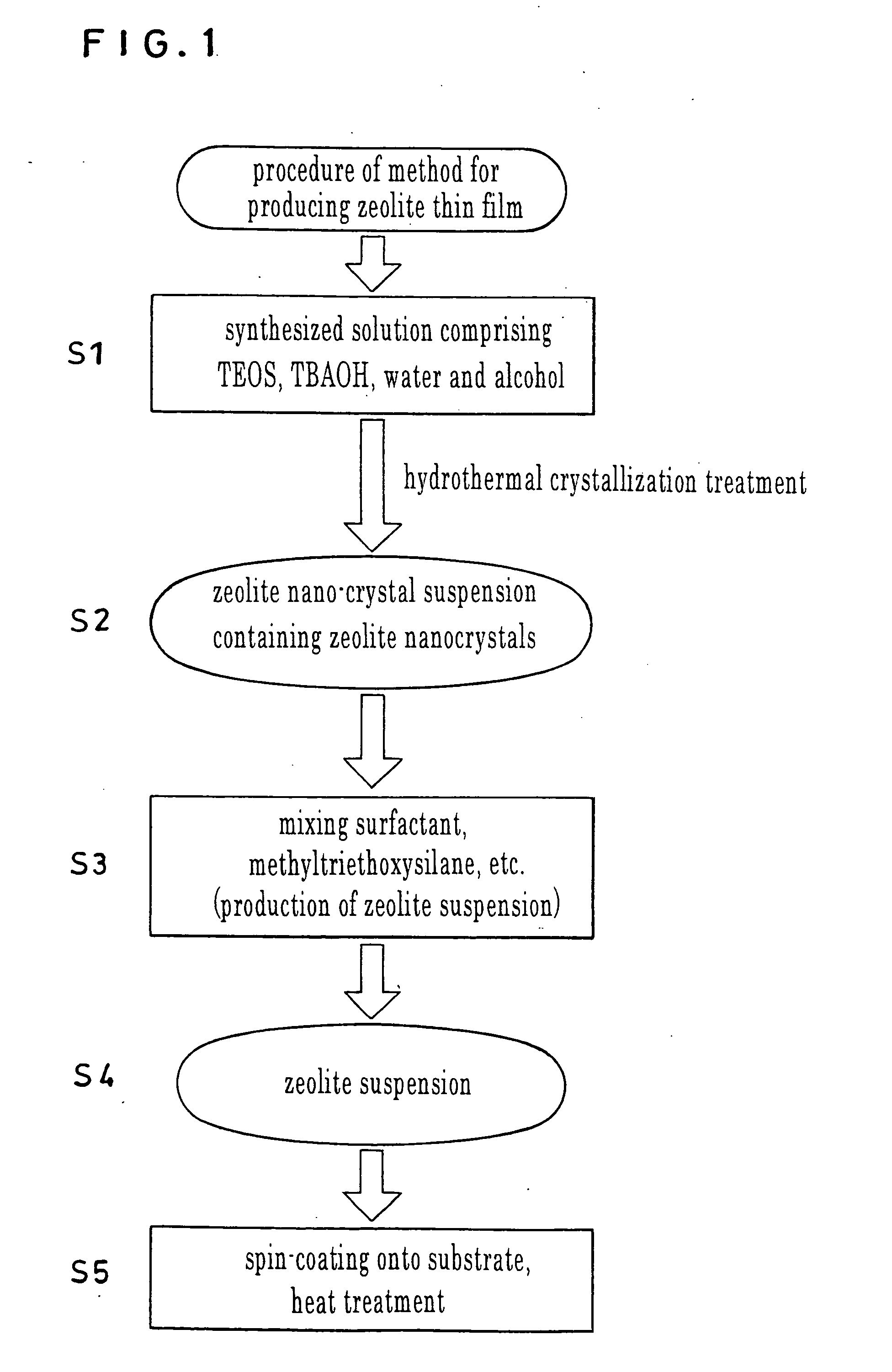
example 1
[0073] To a 40% TBAOH solution under agitation, 15 ml of TEOS was added dropwise. Upon completion of the dropwise addition, 15 ml of ethanol was added to the resultant solution to obtain a mixed solution. The mixed solution was introduced into a cleaned bottle of PFA that was then covered with a cap and retained at room temperature of 23° C. for 20 hours. Subsequently, the PFA bottle containing the mixed solution was placed in an electrical oven, and the mixed solution was subjected to hydrothermal crystallization for 12 hours while being stirred, thereby obtaining a transparent colloidal suspension. The colloidal suspension was then cooled gradually to room temperature of 23° C. to obtain a colloidal suspension (zeolite nano-crystal suspension) of MEL-type pure-silica zeolite (zeolite nanocrystals). The colloidal suspension thus obtained contained no large crystals that had to be removed through centrifugation as was required in the synthesis of an MFI-type pure-silica zeolite susp...
example 2
[0079] In 99 ml of a 1-butanol solution 1 g of tri-block copolymer P123 was dissolved to obtain a composition (ii). A composition (i) synthesized under the same conditions as in Example 1 was thoroughly mixed with the composition (ii) in Example 2 to obtain a liquid. Low-resistivity and high-resistivity silicon wafers 200 mm in diameter were spin-coated with 3 ml of the liquid. The wafer rotation rate during the spin-coating was 2000 rpm, and the spin-coating time was 10 sec. The film obtained was heat-treated in the atmosphere at 90° C. for 2 hours and then calcined at 400° C. for 5 hours. The heating rate at the calcination was 1° C. / min. The film obtained was analyzed and evaluated for the refractive index that was 1.07 and the relative permittivity that was 1.81. The results show the improvements in comparison with the results in Example 1 (the refractive index of 1.12 and relative permittivity of 2.05) in which no composition (ii) was added.
[0080]FIG. 5 shows the effect of the...
example 3
[0081] In 99 ml of 1-butanol 1 g of tri-block copolymer L44 was dissolved to produce a composition (ii). A composition (i) synthesized in accordance with the same method as in Example 1 was thoroughly mixed in an amount of 8 ml with 2 ml of the composition (ii) in Example 3 to obtain a liquid. Low-resistivity and high-resistivity silicon wafers 200 mm in diameter were spin-coated with 3 ml of the liquid. The wafer rotation rate during the spin-coating was 2000 rpm and the spin-coating duration was 10 sec. The film obtained was heat-treated in the atmosphere at 90° C. for 2 hours and then calcined at 400° C. for 5 hours. The heating rate at the calcination was 1° C. / min. The film obtained was analyzed and evaluated for the refractive index that was 1.10 and the relative permittivity that was 1.92. The results show the improvements in comparison with the results in Example 1 (the refractive index of 1.12 and relative permittivity of 2.05) in which no composition (ii) was added.
[0082]...
PUM
| Property | Measurement | Unit |
|---|---|---|
| volume fraction | aaaaa | aaaaa |
| relative permittivity | aaaaa | aaaaa |
| Young's modulus | aaaaa | aaaaa |
Abstract
Description
Claims
Application Information