Bio-chip

a technology of biochips and microorganisms, applied in the field of biochips, can solve the problems of inability to identify species under the microbial genus, difficulty in continuous or real-time on-site monitoring, and technological problems to be solved, so as to avoid dispersing samples and ensure the effect of testing process

Inactive Publication Date: 2006-11-02
KUBOTA LTD
View PDF12 Cites 42 Cited by
  • Summary
  • Abstract
  • Description
  • Claims
  • Application Information

AI Technical Summary

Benefits of technology

[0125] Accordingly, with the present configuration, in testing on a biochip that handles very small amounts of a sample such as a reagent, because it is possible to avoid dissipation of the sample due to evaporation, the testing process can be reliably conducted.

Problems solved by technology

However, under existing circumstances investigation is performed by culture or microscopic observation by an experienced investigator who has brought a sample back to a laboratory, and so it is difficult to perform continuous or real-time on-site monitoring.
In recent years, gene-level detection methods have been reported such as identification by analyzing the base sequence of ribosome RNA genes of microorganisms, but these are all tied to laboratory-level investigation and rarely used on-site, and for the most part are not compatible with identification of species under microbial genus.
However, DNA microarray technology is still in the stages of development, and there are technological problems to be solved.
In their present state, photolithography-type DNA microarrays are expensive due to the time required for design and production, and so their use is limited to only a few research institutions.
On the other hand, in spotting-type DNA microarrays, because DNA probes are fixed on a substrate by dropping minute amounts of liquid droplets including DNA probes on the substrate, there is the problem that droplets that have been dropped spread out on the surface of the substrate, interfering with adjacent spots and causing contamination to occur.
Further, because it is not possible to preserve the density and uniformity of each spot, spotting-type DNA microarrays are also unsatisfactory with respect to precision and reproducibility.
There is also the problem that target DNA is adsorbed nonspecifically on the substrate due to the presence of the solidifying agent affixed around the perimeter of the spot portion, causing an increase in noise and a decrease in the signal-to-noise ratio.
Therefore there is the problem that the fluorescence generated from the substrate itself becomes background noise, reducing the signal-to-noise ratio.
Also, when detecting fluorescence, ordinarily data is acquired by detecting the fluorescence of each spot using a commercially available microarray scanner, but laser oscillators and optical systems are extraordinarily expensive, and for high-precision detection it is necessary to accurately position the spots in the microscanner.
Accordingly, the conventional method cannot be said to be sufficiently satisfactory from the viewpoints of precision, cost, or simplicity of operation.
Thus, gas permeability is high, and when PDMS is used as the main component of the base material that forms the chamber, there is the problem that water inside the chamber evaporates.
Because DNA chips and protein chips have a very small sample as their target, the effect of water evaporation on the reaction system is large, and there is the problem of not being suitable for long-term storage with the sample remaining supported.
Particularly, with DNA chips, water evaporation is a large problem in the step in which a reaction is performed at a high temperature, such as in hybridization.
Also, water evaporation has a particularly large effect when constructing a protein chip, because the structure and activity of protein can only be preserved under moist conditions.
Thus, it cannot be applied to the detection of visible light by enzyme labeling or the like, and laser light detection is required to be performed.
However, although laser light detection is an excellent method with good sensitivity, the cost of detection is high because equipment for detection is expensive.
Although glass has the benefits of being acquired at a low price and having excellent chemical resistance, it has the drawbacks of being difficult to fabricate, and not being suited to uses that employ ultraviolet rays (UV) in a detection system because of the UV absorption of glass.
Thus, it is difficult to immobilize biological molecules and various chemical substances and the like involved in biochemical reactions to the surface of PDMS substrate.
In this sort of property modification of the surface of PDMS substrate, when UV irradiation treatment and UVO treatment are performed on the surface of PDMS substrate, or strong alkali treatment, and there is the problem that cracks occur in the surface of PDMS substrate and it becomes cloudy, and transparency is markedly impaired.
At this time, if transparency of the microreactors is impaired, detection of fluorescence with a scanner becomes difficult and it is not possible to perform accurate DNA analysis.
Also, there is the problem that when oxygen radical irradiation treatment is performed on the surface of PDMS substrate, the generated hydroxyl groups can not be stabilized, and only temporary surface modification occurs.
Also, because an extremely expensive plasma irradiation apparatus or the like is used, there is the problem that production cost becomes high.
High production cost is an obstacle to allowing PDMS to come into widespread use as a constituent material of microreactors.
(target temperature), there is the inconvenience that it takes time to allow the object of temperature control to reach the target temperature.
Also, when the DNA chip is heated when performing DNA amplification, because reaction fluid including sample DNA evaporates from the sample injection hole and sample discharge hole, there is the problem that reliable execution of the testing process is difficult.

Method used


Image

  • Bio-chip
  • Bio-chip
  • Bio-chip

Examples


embodiment 1

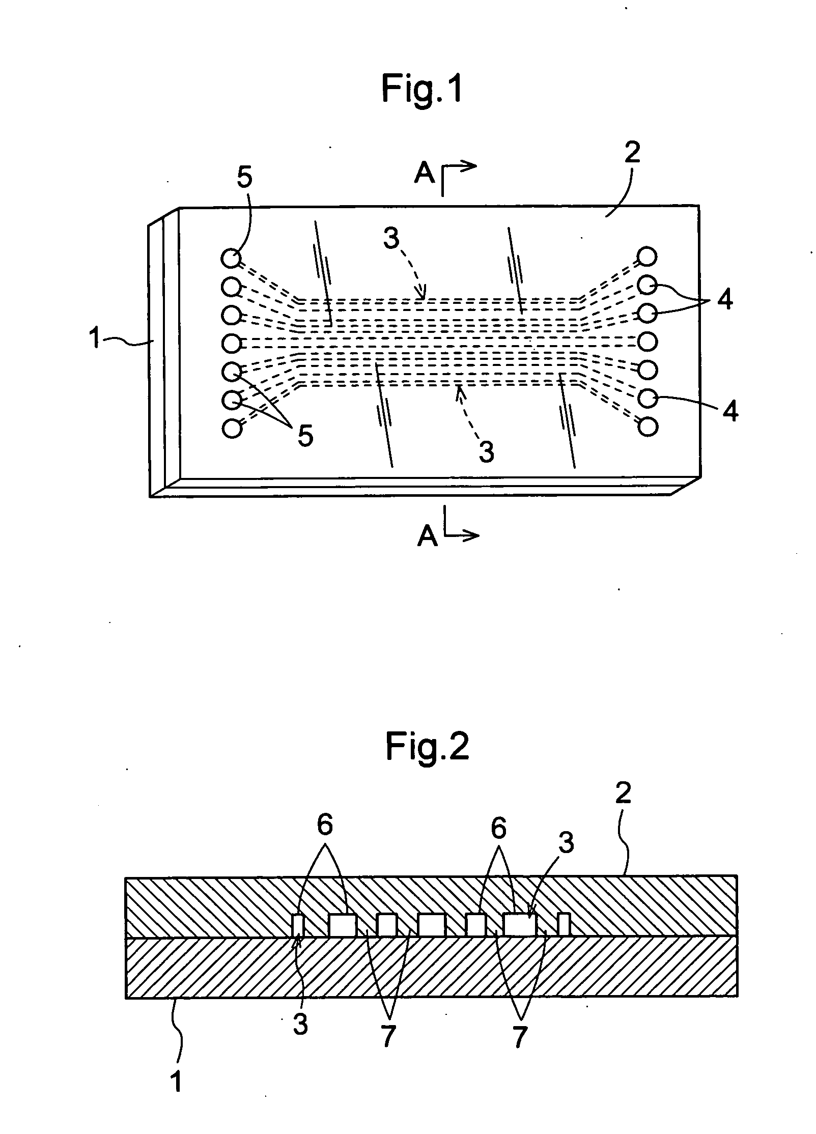
[0128]FIG. 1 is a schematic view that shows the basic configuration of the present invention, and is a top view of the barcode array of the present invention. FIG. 2 is a cross-section taken along line A-A in FIG. 1, and schematically shows the barcode array of the present invention when it has been configured as Embodiment 1-1. Below, the top side in FIG. 2 is referred to as the “top”, and the bottom side is referred to as the “bottom”.

[0129] As shown in FIGS. 1 and 2, the barcode array of the present invention is configured from a first member 1 and a second member 2 fixedly disposed on the top face of the first member 1, and spaces that become reaction regions 3 disposed in a barcode shape are provided between the first member 1 and the second member 2.

[0130] The first member 1 is configured as a flat plate-shaped body. Surface treatment is performed on flat plate-shaped substrate of the second member 2, and a plurality of grooves 6 that extend in one direction are formed in pa...

embodiment 1-2

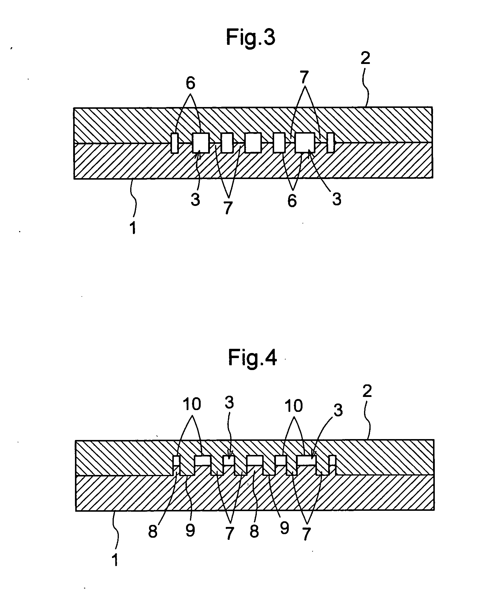
[0155] Next, the barcode array of embodiment 1-2 of the present invention is described with reference to FIG. 3. FIG. 3 is a is a cross-section taken along line A-A in FIG. 1, and shows the barcode array of the present invention when it has been configured as Embodiment 1-2. Parts of the configuration that are the same as the barcode array of Embodiment 1-1 have the same reference numerals in FIG. 3, and their explanation is omitted here.

[0156] With respect to both the first member 1 and the second member 2, surface treatment is performed on flat plate-shaped substrate, and a plurality of grooves 6 that extend in one direction are formed in parallel in a barcode shape on the surface that contacts the other member. That is, both the first member 1 and the second member 2 have a space structure in which a plurality of line-shaped grooves 6 alternate with dividing walls 7 that partition the grooves 6. The first member 1 and the second member 2 are configured so that when they have bee...

embodiment 1-3

[0158] Next is a description of the barcode array of Embodiment 1-3 of the present invention with reference to FIG. 4. FIG. 4 is a is a cross-section taken along line A-A in FIG. 1, and schematically shows the barcode array of the present invention when it has been configured as Embodiment 1-3. Parts of the configuration that are the same as the barcode array of Embodiment 1 have the same reference numerals in FIG. 4, and their explanation is omitted here.

[0159] With respect to both the first member 1, surface treatment is performed on flat plate-shaped substrate, and a plurality of linear convex portions 8 that extend in one direction are formed in parallel in a barcode shape on the surface that contacts the second member 2. With respect to the second member 2 as well, surface treatment is performed on flat plate-shaped substrate, and a plurality of linear groove portions 10 that can be fitted one-to-one with the linear convex portions 8 are formed in parallel on the surface that ...


PUM

PropertyMeasurementUnit
current temperatureaaaaaaaaaa
sizeaaaaaaaaaa
widthaaaaaaaaaa

Abstract

A biological molecule biochip that supports biological molecules between a first member and a second member; in either the first member or the second member, by forming a plurality of grooves in parallel in a face that makes contact with the other member, a plurality of spaces are provided that become reaction regions.

Description

TECHNICAL FIELD [0001] The present invention relates to biochips used for determining information regarding nucleic acid sequences and analysis of expression, variation, diversity, and the like of genes, as well as refinement and identification of target proteins and functional analysis of protein expression, interaction, posttranslational modification, and the like, and more specifically relates to the shape, microstructure, surface modification, and temperature control of biochips. BACKGROUND ART [0002] Conventionally, in the market of environmental business there is a strong demand to reliably know the movement of microorganisms that are problems in the fields of soil purification and water safety. That is, there are demands to monitor the presence of pathogenic microorganisms that exist in water supply and sewage systems sequentially or in real time, and to quickly and accurately identify and quantify coliform bacteria, intestinal bacteria, and the like, which are water safety s...

Claims


Application Information

Patent Timeline
Patent Type & Authority Applications(United States)
IPC IPC(8): C12M1/34B01L3/00C12M1/00C12N15/09G01N33/53G01N35/00G01N37/00
CPCB01L3/502707B29C66/961B01L2300/021B01L2300/0816B01L2300/0861B01L2400/0406B29C65/002B29C66/12441B29C66/54B29K2033/08B29K2033/12B29K2709/08B29L2031/756G01N2035/00158G01N2035/00376B01L2200/0689B29C66/91655B29C66/91212B29C66/91231B29C66/91411B29C66/91421B29C65/00B29C66/71
Inventor KURANE, RYUICHIROTORIYAMA, AKIOEZAKI, SATOSHIKOWADA, HIROMITSUSHIRAIWA, YUKI
Owner KUBOTA LTD
Why Eureka
Try Eureka