Tangential flow filtration apparatuses, systems, and processes for the separation of compounds

a tangential flow and filtration technology, applied in the separation process, multi-stage water/sewage treatment, membranes, etc., can solve the problems of increasing the risk of product contamination, increasing the risk of operators, and increasing the cost of production, so as to improve the purity and other superior characteristics, improve the efficiency of filtration, and improve the effect of operation temperature control

Inactive Publication Date: 2007-10-25
GENENCOR INT INC
View PDF4 Cites 93 Cited by
  • Summary
  • Abstract
  • Description
  • Claims
  • Application Information

AI Technical Summary

Benefits of technology

[0015] According to various embodiments, the filtration system has a control system that can provide independent adjustment of one of product yield, product purity, net permeation rate, and overall flux while maintaining the three other variables approximately constant. The configuration of the system exemplified herein allows it to be amenable to such independent control over these operational parameters. Conventional TFF machines and processes such as identified herein do not have multiple permeate streams (i.e., recycle, backfeed, withdrawal) at the filtration modules as provided in various embodiments of this present invention, nor the ability to control them independently. It is these multiple permeate streams and control of the above operating parameters that can provide more precise and predictable control of process parameters and product quality in various embodiments of the present invention. As shown by examples described herein, products produced by the system and process of the present invention have improved purity and other superior characteristics as compared to products produced by traditional filtration systems (e.g. R

Problems solved by technology

A major drawback of various technologies is the requirement for repeated addition of raw materials to accomplish the filtration or separation.
This can increase the cost of production significantly, and these materials may have to be tailored to provide a specific maximum particle size that is allowed to pass.
Some processes can be exposed to the environment and increase the risk of contamination of the product as well as risk to operators from exposure to filter aids, raw broths, and products.
Further, separated protein fractions produced by these technologies can have a much larger particle size distribution, and lower

Method used


Image

  • Tangential flow filtration apparatuses, systems, and processes for the separation of compounds
  • Tangential flow filtration apparatuses, systems, and processes for the separation of compounds
  • Tangential flow filtration apparatuses, systems, and processes for the separation of compounds

Examples


example 1

[0209] A set of experiments was conducted that demonstrated the advantage of the TFF microfiltration system during the microfiltration purification of glucoamylase enzyme from a fermentation broth composed of a mixture of corn steep solids, salts and a carbon nutrient. In the experiment, a Koch membrane module (Koch Systems, Wilmington, Mass.) Model MFK-601-FYT (8338) was used in this Example. A similar module was used in Examples 2 and 3 except for a smaller diameter (3838). The production host was Aspergillus niger. At the end of fermentation, the pH of the broth was adjusted to about pH 3.3 with sulfuric acid; 3.5% bentonite was added to the broth; and the broth was held for a minimum of 12 hours before beginning the microfiltration process. No water or diafiltration solution was added to the broth before the start of the clarification process, and no flocculants or filter aids were used for these experiments.

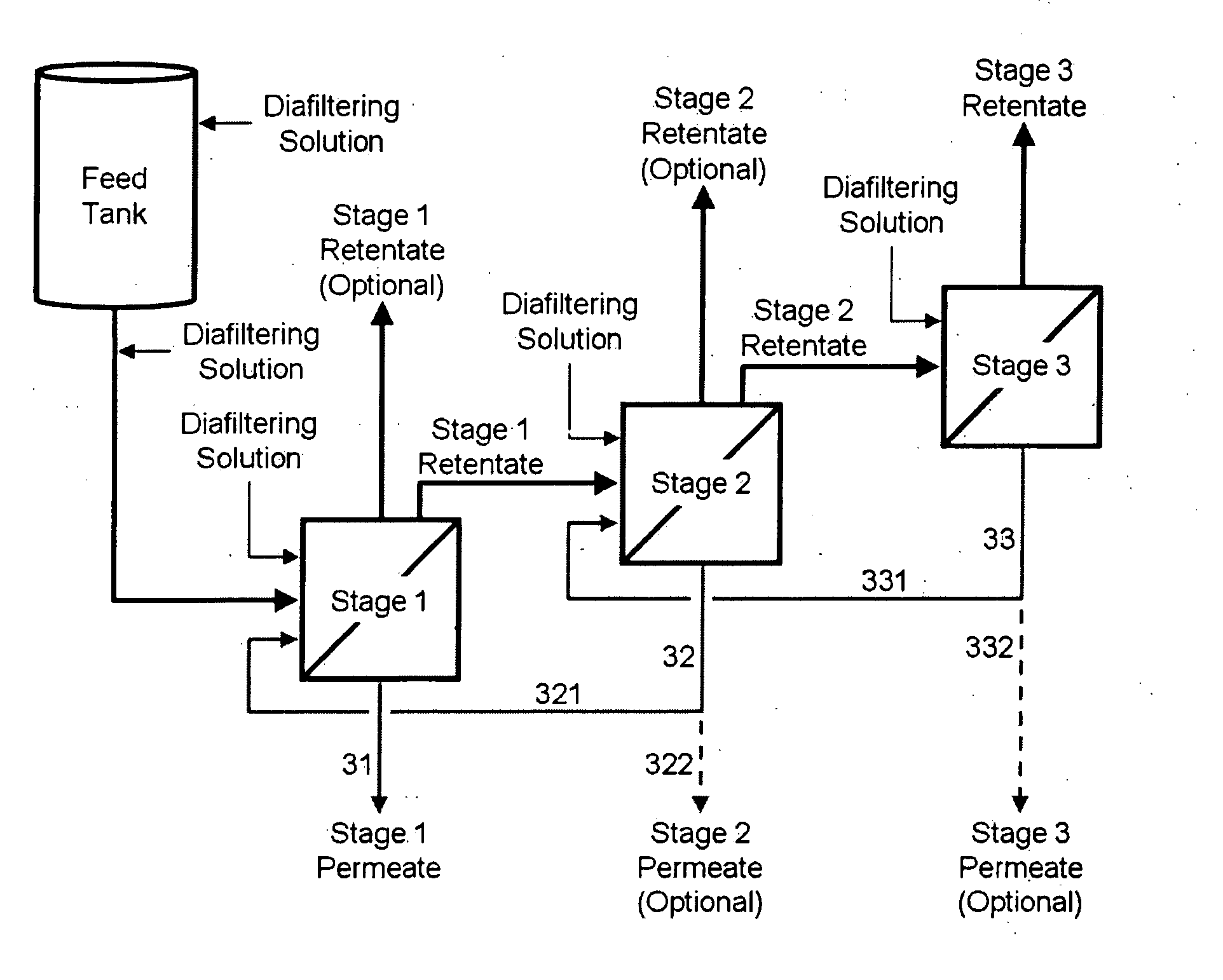
[0210] Compared to a traditional TFF system, the system of the applica...

example 2

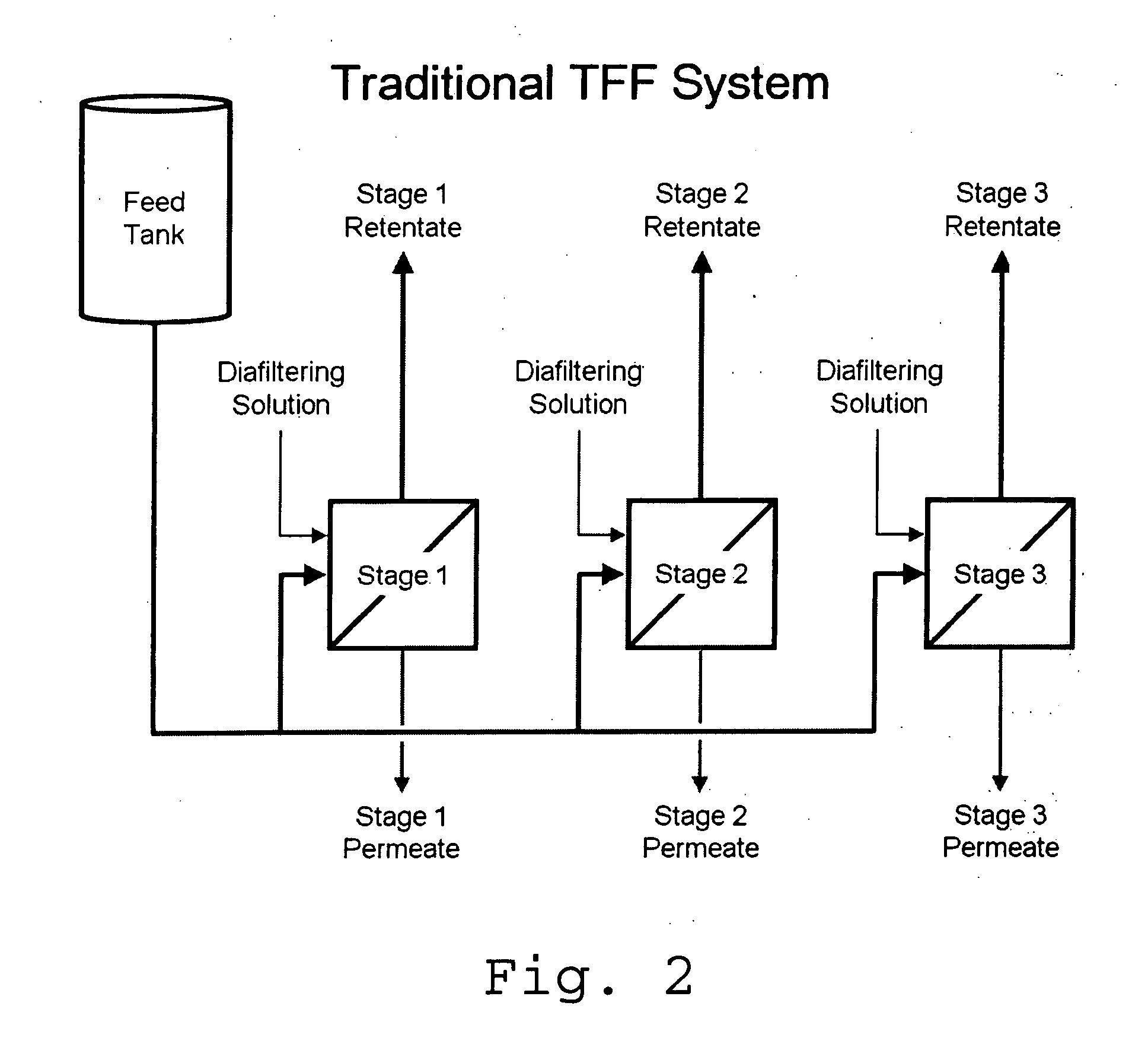
[0213] Results in FIG. 6 was obtained with a conventional TFF system using a microfiltration membrane and a feed consisting of B. subtilis broth and protease enzyme. The results provide information concerning altering TMP and the effect on flux and passage of material through the membrane in a filtration unit (a simplified version of FIG. 2 with one stage).

[0214]FIG. 6 illustrates that for a product using low TMP pressures where traditional MF machines operate, the passage of the protein is sufficient to be able to operate up to about 0.9 bar TMP and have passages of 70% or above, with a flux rate of about 28 L / m2 / h (lmh). The TFF microfiltration apparatus / system described herein, however, could operate at a higher TMP of about 1.5 bar, and despite a passage of about 40%, could achieve over all yield of 90-92%, (see Example 1).

[0215]FIG. 7 provides another illustration of how the counter-current machine can provide a benefit. It shows data from three separate experiments demonstra...

example 3

[0217] Table 1 lists several products that were obtained using the systems and methods described herein. These products made from either bacterial or fungal broth represent enzymes, each with unique properties although some may share similar enzymatic function and are said to be of a particular type, for example alpha-amylase #1 through #4. Various parameters used in obtaining the products are also listed herein.

TABLE 1Products and Production ParametersDelta PInlet sideInlet sideDiafiltration-(bar perfeed pressureexit pressureto-brothConcentrationProductelement)(bar)(bar)ratioratioAlpha-amylase #10.5-1.51.5-4.50.5-1.52.0-6.00.3-1.0Alpha-amylase #20.5-1.51.5-5.50.5-3.02.0-6.00.3-1.0Alpha-amylase #30.5-1.51.5-4.00.5-2.52.0-6.00.3-1.0Alpha-amylase #40.5-1.51.5-3.50.5-2.02.0-6.00.5-1.0Cellulase #10.5-1.51.5-3.50.5-2.02.0-6.00.3-1.0Cellulase #20.5-1.51.5-5.50.5-3.52.0-6.00.3-1.0Glucoamylase0.5-1.51.5-3.50.5-1.02.0-6.00.3-1.0Mannanase0.5-1.01.5-3.00.5-1.02.0-6.00.3-1.0Peroxidase0.5-1.01...


PUM

PropertyMeasurementUnit
Temperatureaaaaaaaaaa
Fractionaaaaaaaaaa

Abstract

The invention relates to apparatuses, machines, systems and methods for the recovery and purification of proteins, peptides, nucleic acids, biologically produced polymers and other compounds from aqueous fluids. The aqueous fluids can comprise enzyme concentrates and or a fermentation broth with or without cells or other starting material. The fermentation broth can be produced by fermentations of fungal, yeast, bacterial, mammalian, insect or plant cells.

Description

CROSS-REFERENCE TO RELATED APPLICATIONS [0001] This application claims benefit of priority to U.S. Provisional Application No. 60 / 788,125, filed Mar. 31, 2006, which is hereby incorporated by reference in its entirety.INTRODUCTION [0002] The section headings used herein are solely for organization purposes and are not to be construed as limiting the subject matter described in any way. [0003] The present invention relates to apparatuses, systems and methods for the separation, recovery, and / or purification of proteins, peptides, nucleic acids, biologically produced polymers and other compounds from aqueous fluids. The aqueous fluids can comprise a fermentation broth with or without cells or other starting material. The fermentation broth can be produced by fermentations of fungal, yeast, bacterial, mammalian, insect or plant cells. BACKGROUND [0004] Microfiltration has been used for separation of compounds in biological broths or other liquids. The beverage industry has employed mic...

Claims


Application Information

Patent Timeline
IPC IPC(8): B01D61/00
CPCB01D61/142B01D61/147B01D61/16B01D61/20B01D2311/04B01D2315/10B01D61/22B01D2317/022B01D2315/16B01D61/18C12M47/10C12M47/12B01D2311/16B01D61/146B01D61/1471B01D61/149
Inventor DIBEL, KEVIN R.FONG, ROBINHENG, MENG H.ROZEBOOM, GLENN
Owner GENENCOR INT INC
Why Eureka
Try Eureka