
Polymer Films

a technology of polymer films and films, applied in the field of polymers, can solve the problems of difficult control of the thickness of the layer, high density of the grafted chain, etc., and achieve the effect of high yield of useful particles

Inactive Publication Date: 2008-02-07
MIP TECH AB
View PDF2 Cites 8 Cited by
  • Summary
  • Abstract
  • Description
  • Claims
  • Application Information

AI Technical Summary

Benefits of technology

[0012] According to another embodiment this invention relates to the combination of approaches (A) and (B) (see Background art) to generate defined nanostructures. This presents a number of new and previously unexplored opportunities (FIG. 6). Especially cross-linked polymers may form walls of a porous material or the shell of hollow spheres. For instance, grafting a thin film onto a disposable support and subsequently removing the support would leave behind a porous material with thin walls (FIG. 6A). If the walls are made very thin (e.g. 1-5 nm), these materials exhibit no permanent porosity and instead behave as gels with high swelling factors. In the swollen state they should ideally exhibit a 2-fold larger surface area than the precursor support material. By analogy with hydrogels, such gel-like materials could further exhibit stimulus-response functions, e.g. a chemically or physically triggered change in swelling.8 If the grafting is performed under CRP conditions, multiple layers may be grafted exhibiting different composition, structure and function. After removing the support the innermost layer (the first grafted layer) would be exposed within walls which thus would contain two non-equivalent surfaces (FIG. 6B). In a simple case the polarity of the layers can be different, layer (a) can be composed of a hydrophilic polymer whereas layer (b) can be composed of a hydrophobic polymer. After support removal, a porous material with walls containing one hydrophobic and one hydrophilic surface would be obtained. Depending on the support material morphology these thin walled materials can be further designed to exhibit a high surface area. This could be used to enhance the efficiency in liquid-liquid two phase extractions where the hydrophobic pores would be filled with the organic phase and the hydrophilic with the aqueous phase.
[0013] Another possibility using this layer by layer approach would be to facilitate chemical reactions or catalyze chemical reactions within the layer or film. This can occur either through reactions occurring at the oil / water interface combined with facilitated transport of the reactants or products and / or incorporation of catalytically active groups within the thin walls. Both of these approaches would benefit from the potentially high surface area of the thin walls, the short diffusion paths through the walls and the polarity difference between the surfaces. Thus in the case of one nonpolar surface exposed to an organic solvent and one polar exposed to water (see FIG. 6B) interfacial reactions can be performed with a higher efficiency than is possible using classical two phase reactions in liquid-liquid two phase systems. This can for instance be the hydrolysis of a lipophilic ester (or amide) to hydrophilic products being the corresponding alcohol (or amine) and acid. The reactant(s) easily adsorb at the non-polar surface whereas the product will be released from the polar surface into the aqueous phase (FIG. 6C). The catalysis of the reverse condensation reaction is also possible.
[0017] In another approach (the hierarchical imprinting approach) porous silica is used as a mould in order to control the particle size, shape and porosity of the resulting imprinted polymer.6 The template can either be immobilized to the walls of the mold or the template can be simply dissolved in the monomer mixture. The pores are here filled with a given monomer / template / initiator mixture, and after polymerization the silica is etched away and imprinted polymer beads are obtained exhibiting molecular recognition properties. From a production stand point this procedure has the advantage of being simple and of giving a high yield of useful particles with predefined and unique morphology.

Problems solved by technology

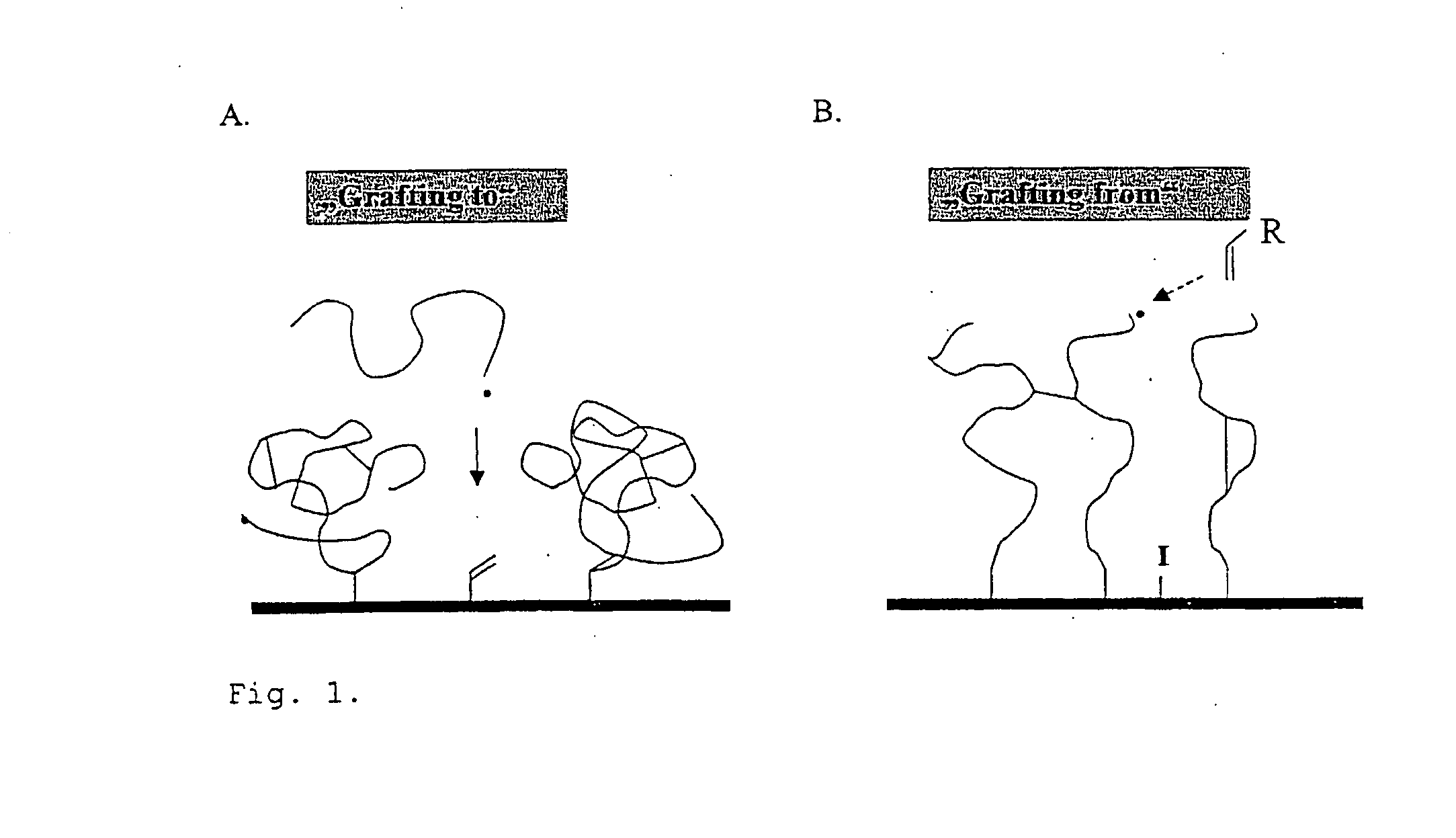
This leads to reactions mainly between monomers and surface confined radicals resulting in a high density of grafted chains.
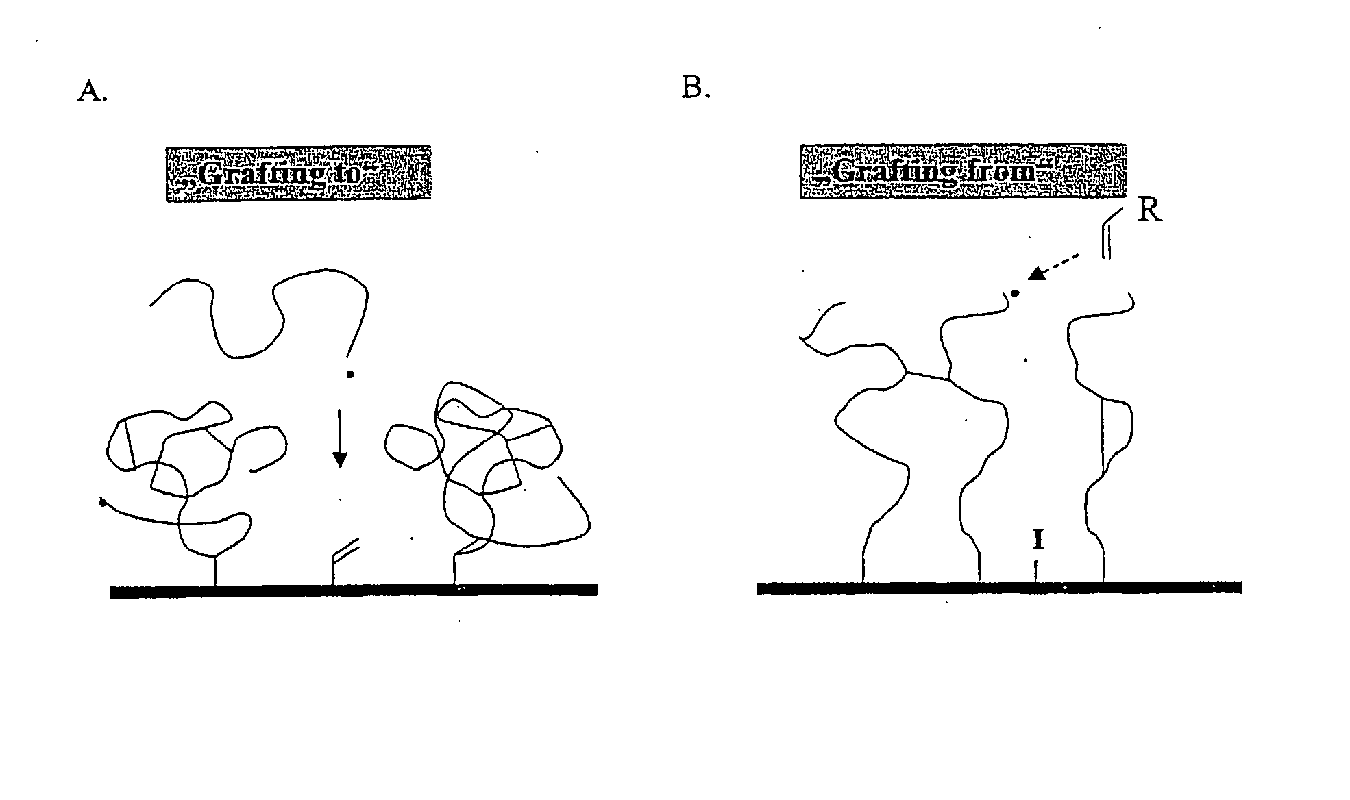
By performing the grafting under conventional polymerization conditions, the thickness of the layers is difficult to control and significant propagation occurs in solution.

Method used


Image

  • Polymer Films
  • Polymer Films
  • Polymer Films

Examples


example 1

Imprinted (MIP) and Nonimprinted (MP) Polymer-Silica Composites Using Immobilized Azo-Type Initiators and RAFT Polymerization.

[0049] Porous Si100 particles (average pore diameter (d)=10 nm) were modified with azoinitiator in two steps,12 before grafting of a polymer film on its surface. Prior to the first modification step, the silica surface was rexydroxylated according to standard procedures. This is known and result in a maximum density of free silanol groups of ca. 8 μmol / m2. A maximum of half the silanol groups reacted with (3-aminopropyl)triethoxysilane (APS) in the first silanization steps. The subsequent step was the attachment of azobis(cyanopentanoic acid) ACPA. On the basis of the increase in nitrogen content, a maximum area density of 1.5 μmol / m2 for the azo-initiator.

[0050] 1 g of this azo-modified silica particles was suspended in a polymerization mixture containing L-phenylalanine anilide (L-PA) (0.240 g), RAFT agent (2-phenylprop-2-yl-dithiobenzoate) (0.2 g), MAA ...

example 2

Imprinted (MIP) and Nonimprinted Polymer-Silica Composites Using Iniferter-Type Initiators

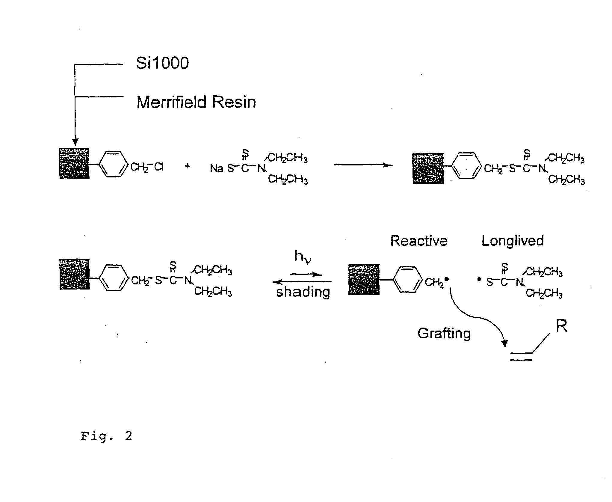
[0051] Prior to the first modification step, the silica surface was rexydroxylated according to standard procedures. This is known to result in a maximum density of free silanol groups of ca. 8 μmol / m2. A maximum of half the silanol groups reacted with p-(chloromethyl)phenyltrimethoxy silane in the first silanization steps. The subsequent step was the conversion of the benzylchloride groups to the corresponding diethyldithiocarbamate by reaction with sodium-N,N-diethyldithiocarbamate. On the basis of the increase in nitrogen and sulphur content, a maximum area densities of 0.75 μmol / m2 for the iniferter was calculated.

[0052] 1 g of iniferter-modified silica particles was suspended in a polymerization mixture containing L-PA (0.240 g), MAA (0.68 mL) and EDMA (7.6 mL) dissolved in 11.2 mL of dry toluene. The polymerization was carried out as described in example 1.

[0053] Non-imprinted control...

example 3

[0054] Imprinted (MIP) and Nonimprinted Hydrophilic Polymer-Silica Composites Using Iniferter-Type Initiators

[0055] 1 g of iniferter-modified silica particles, obtained as described in Example 2, was suspended in a polymerization mixture consisting of L-PA (0.04 g), MAA (0.172 mL), HEMA (0.49 mL) and EDMA (1.26 mL) dissolved in 3 mL of dry 1,1,1-trichloroethane. The polymerization was carried out as described in example 1.

[0056] Non-imprinted control polymer composites (NIP) were prepared as described above but without addition of the template.


PUM

PropertyMeasurementUnit
Hydrophilicityaaaaaaaaaa

Abstract

This invention relates to a non-supported (or free standing) cross linked polymer film obtainable by initiating the polymerization of one or several monomers at an interphase. The interphase may be between two immiscible liquids or at a liquid-gas, solid-gas or solid-liquid interphase. The polymer may be used to facilitate chemical reactions, for separation of substances, as a chromatographic stationary phase, as an adsorbent, in sensors or actuators. It may also be used for drug delivery, as a responsive valve or in artificial muscles. The invention also relates to a method for producing thin film polymers, wherein controlled radical polymerization (CRP) is used to produce a thin film cross-linked polymer at an interface where one of the phases (liquid, solid or gas) can be removed after polymerization and be replaced with another phase (liquid, solid or gas).

Description

TECHNICAL FIELD OF THE INVENTION [0001] The present invention relates to polymers in the form of free standing films or layers. The films or layers can form the walls of a porous material or the shell of hollow spheres. BACKGROUND ART [0002] The ability to control the structure and composition of materials on a nanometre scale is key to a number of advanced functions within diverse areas such as drug delivery, diagnostics and sensing, molecular electronics, catalysis, separations or in mimicking biological systems.1 While nature has mastered this task, several synthetic so called “bioinspired” approaches have appeared leading to materials mimicking various morphologies found in nature such as molecules or particles with a core-shell structure, as membranes or vesicles. These can further incorporate other design principles used by nature such as compartmentalization and self assembly for such advanced functions as transport, molecular recognition or catalysis. Robust synthetic approa...

Claims


Application Information

Patent Timeline
IPC IPC(8): C08F265/02C08K5/16B01J20/285B32BC08F251/00C08F257/02C08F265/00C08F265/04C08F283/00C08F290/00C08F291/00C08F293/00C08L51/00
CPCB01J20/268B01J20/285C08F251/00C08F257/02C08F265/00C08F265/04C08F283/00C08L51/003C08F290/00C08F291/00C08F293/005C08J5/18C08L2666/02
Inventor SELLERGREN, BORJETITTIRICI, MAGDALENA M.
Owner MIP TECH AB
Learn More