
Method of Production of a Conductive Particle, Conductive Paste, and Method of Production of Electronic Device

a technology of conductive particles and conductive paste, which is applied in the direction of non-conductive materials with dispersed conductive materials, fixed capacitors, solid-state diffusion coatings, etc., can solve the problems of internal electrode layers cracking or peeling, high cost of multi-layer ceramic capacitors, and high cost of precious metals, so as to prevent spheroidization and reduce the electrostatic capacity. , the effect of preventing electrode disconnection

Inactive Publication Date: 2008-02-14
TDK CORPARATION
View PDF5 Cites 12 Cited by
  • Summary
  • Abstract
  • Description
  • Claims
  • Application Information

AI Technical Summary

Benefits of technology

[0060] Ru, Rh, Re, and Pt are precious metals with melting points higher than Ni. Further, coating layers having these metals or alloys as main ingredients are superior in wettability and bondability with the dielectric layers. Therefore, by using conductive particles having cores having Ni as their main ingredients on which these coating layers are formed so as to form internal electrode layers, even if the internal electrode layers are made thinner, it is possible to suppress the growth of Ni particles in the firing stage and effectively prevent spheroidization, electrode disconnection, etc. and effectively suppress reduction of the electrostatic capacity. Further, delamination between the internal electrode layers and dielectric layers can also be prevented. Further, no firing defects of the dielectric powder will occur.
[0061] Further, according to the method of production of the present invention, it is possible to produce conductive particles optimm as conductive particles to be included in electrode paste for forming the internal electrode layers of an electronic device having internal electrode layers and dielectric layers with a high efficiency without the occurrence of abnormal segregation (segregated particles of a size of several μm). That is, according to the method of production of the present invention, it is possible to prevent the formation of segregated particles of a precious metal (for example, Pt) of a size of several μm and form good Pt or other coating layers on the surfaces of the Ni particles or other core powder of 200 nm size or less.
[0062] In the present invention, the water-soluble polymer compound or surfactant is believed to act so that when the precious metal (for example Pt) particles are formed by the addition of the reducing agent, the polymer compound molecules or surfactant molecules are adsorbed on the surfaces of the precious metal particles and prevent direct contact between precious metal particles or suppress agglomeration or segregation to a size of several μm.

Problems solved by technology

However, precious metals are themselves expensive.
As a result, there was the defect that the finally obtained multilayer ceramic capacitors became high in cost.
If sintering at the higher temperature when there is a large difference in the sintering temperatures, the internal electrode layers will crack or peel off, while if sintering at the lower temperature, firing defects of the dielectric powder will sometimes occur.
As a result, it becomes difficult to continuously form fired internal electrode layers.
When the fired internal electrode layers are not continuous, there is the problem that the multilayer ceramic capacitor falls in electrostatic capacity.
However, this Patent Document 1 considers control of the alloy difficult with the thin film formation method, prepares internal electrode layers made of multilayer metal films before firing, and alloys them in the firing stage.
However, this Patent Document 1 does not disclose anything regarding what kind of metal may be used to alloy with so as to suppress growth of nickel particles in the firing stage and prevent spheroidization so as to prevent electrode disconnection when using internal electrodes having nickel as their main ingredients.
Depending on the composition forming the multilayer metal films, conversely the sintering temperature ends up being lowered and growth of the nickel particles in the firing stage cannot be suppressed.
Further, when the metal film contacting a ceramic when forming a multilayer metal film is poor in wettability and bondability with the ceramic, conversely spheroidization and disconnection end up occurring and the capacitor falls in electrostatic capacity.
However, to produce the above conductive particles, in the case of alloy particles, there was the problem that the steps were increased such as by the sputtering and the production process became longer.
Therefore, there was the problem of a poor efficiency of production of platinum-coated nickel particles.
Therefore, there were limits with the art described in Patent Document 4 when trying to use an easily oxidizable substance such as Ni as the main metal material of the internal electrodes.

Method used

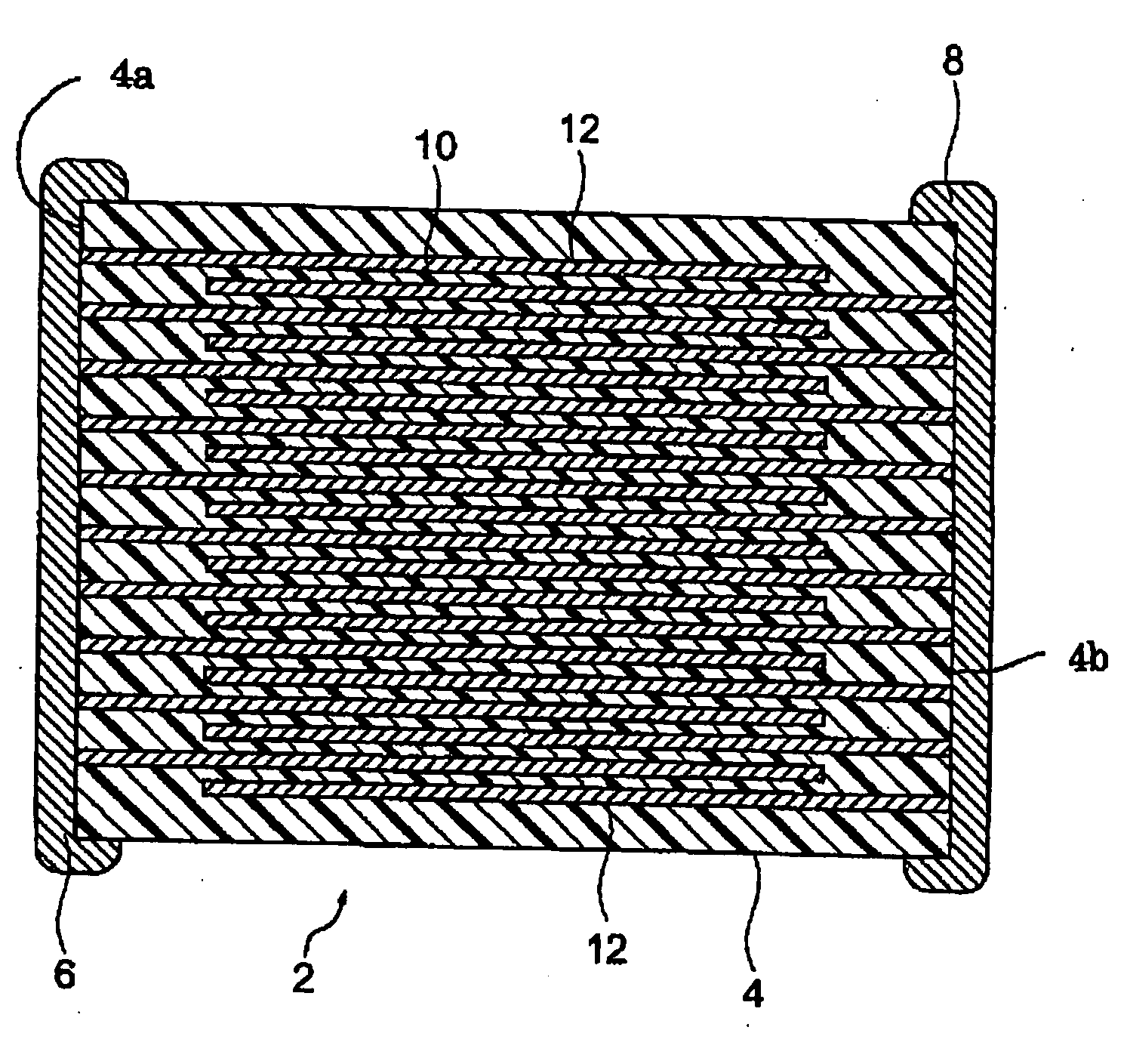

Image

  • Method of Production of a Conductive Particle, Conductive Paste, and Method of Production of Electronic Device
  • Method of Production of a Conductive Particle, Conductive Paste, and Method of Production of Electronic Device
  • Method of Production of a Conductive Particle, Conductive Paste, and Method of Production of Electronic Device

Examples


example 1

[0129] This example was performed in a glove box with an N2 flow with an oxygen content of 0.005 vol %.

[0130] 1 g of Pt chloride hydrate was dissolved in 1 liter of water, then 1 g of PVA (one example of a water-soluble polymer compound) with a saponification degree of 88 mol % (0.1 wt % with respect to Pt chloride aqueous solution) was added and the mixture vigorously stirred to prepare a Pt chloride aqueous solution. Next, 13 g of an Ni powder having an average particle size of 100 nm was charged into the Pt chloride aqueous solution and the result stirred to prepare an aqueous dispersion.

[0131] Further, separate from this aqueous dispersion, 0.47 g of hydrazine hydrate 80% was added to 470 ml of water and the two mixed uniformly to prepare a hydrazine aqueous solution.

[0132] Next, the previously prepared Pt chloride aqueous solution containing Ni powder was vigorously stirred at room temperature while slowly adding a hydrazine aqueous solution at a rate of about 10 ml / min. By ...

example 2

[0134] Except for replacing the PVA with another example of a water-soluble polymer compound, that is, a copolymer of methyl acrylate and acrylic acid (acid value 10 mgKOH / g, molecular weight of 100,000), the same procedure was followed as in Example 1 to produce conductive particles. This was observed in the same way as in Example 1.

[0135] The heat treated powder obtained in this example was examined under a scanning electron microscope, whereupon it was found there was no Pt segregation. Further, when observed under a TEM, it was confirmed that tens of Pt particles of 10 nm or less were deposited on the surfaces of the Ni particles.

example 3

[0136] Except for replacing the PVA with the use of an acetylene diol-based non-ionic surfactant (HLB value 10), the same procedure was followed as in Example 1 to produce conductive particles which were examined in the same way as in Example 1.

[0137] The heat treated powder obtained in this example was examined under a scanning electron microscope, whereupon it was found there was no Pt segregation. Further, when observed under a TEM, it was confirmed that tens of Pt particles of 10 nm or less were deposited on the surfaces of the Ni particles.


PUM

PropertyMeasurementUnit
lengthaaaaaaaaaa
thicknessaaaaaaaaaa
partial pressureaaaaaaaaaa

Abstract

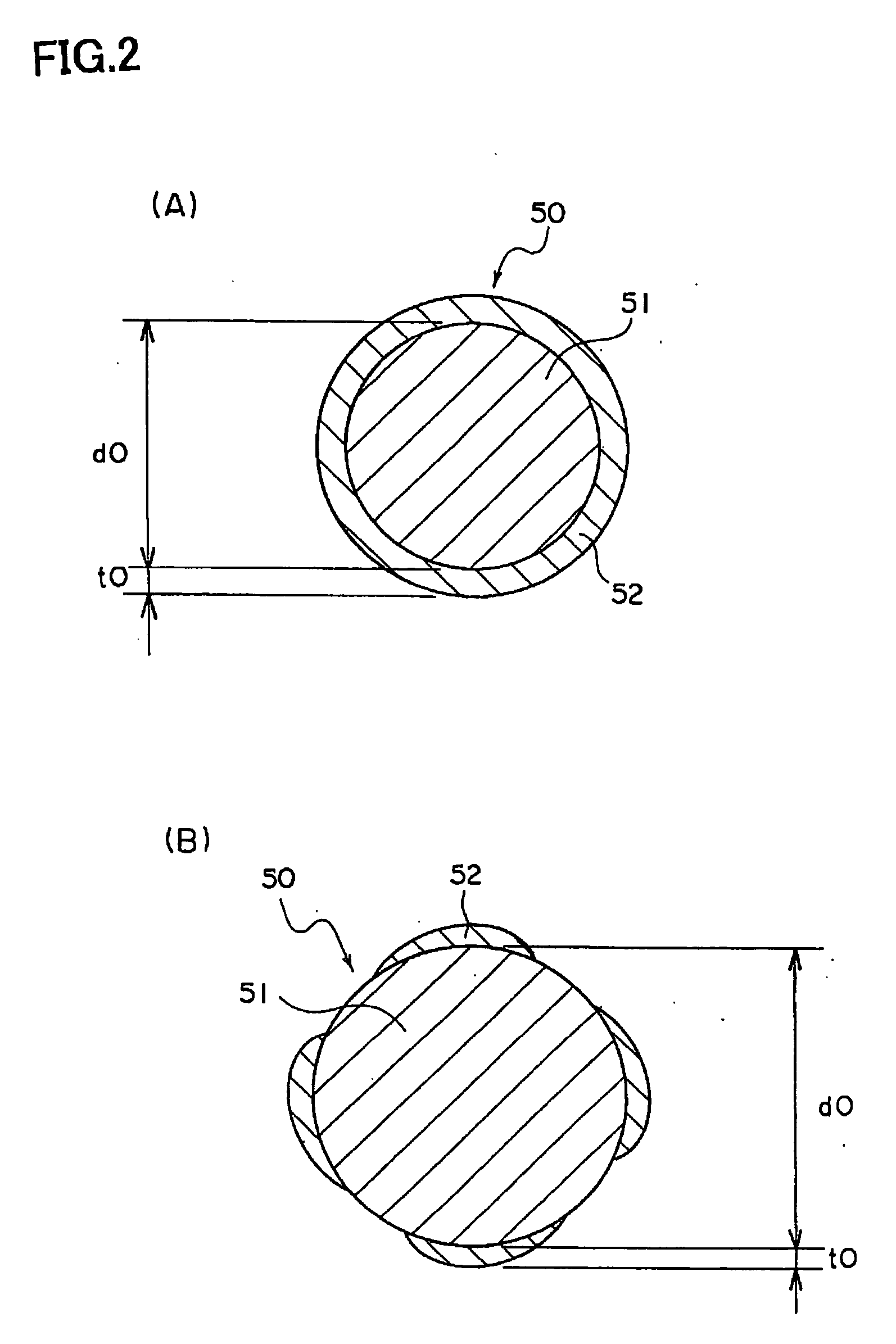
A method of production of conductive particles able to suppress growth of the conductive particles at the firing stage, able to effectively prevent spheroidization and electrode disconnection, able to effectively suppress a drop in electrostatic capacity, and able to efficiently produce core particles covered by thin coating layers without abnormal segregation of the coating layer metal particularly even when the internal electrode layers are reduced in thickness. A method of producing conductive particles comprising cores 51 having nickel as their main ingredients and coating layers 52 covering their surroundings. A core powder, a water-soluble metal salt containing a metal or alloy forming the coating layers 52, and a surfactant (or water-soluble polymer compound) are mixed to deposite by reduction a metal or alloy for forming the coating layers 52 on the outer surfaces of the core powder. The metal or alloy forming the coating layers 52 has at least one type of elements selected from Ru, Rh, Re, and Pt as a main ingredient.

Description

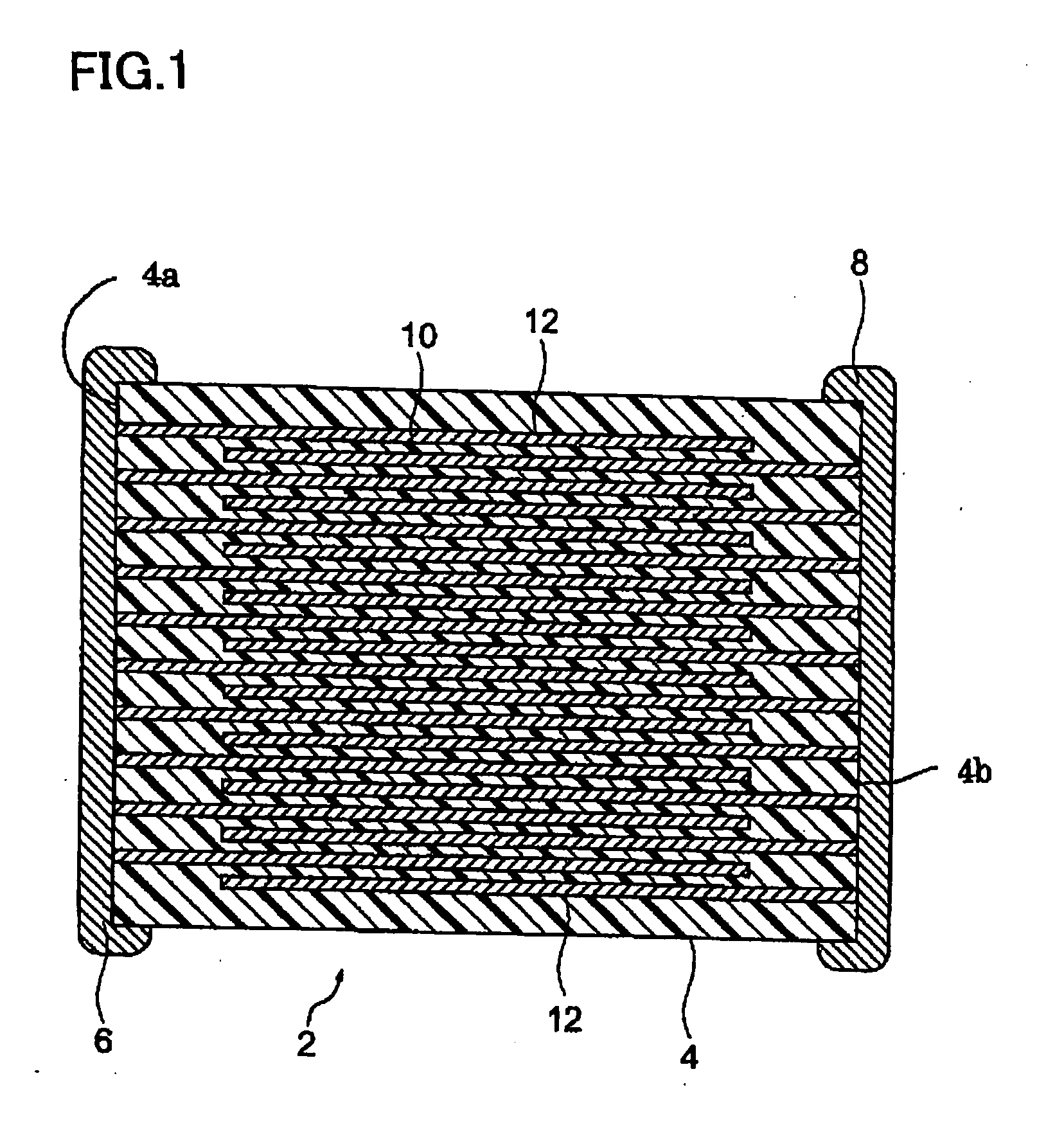
TECHNICAL FIELD [0001] The present invention relates to method of production of conductive particles, a conductive paste, and a method of production of an electronic device. BACKGROUND ART [0002] A multilayer ceramic capacitor, one example of an electronic device, is comprised of a multilayer structure device body including pluralities of dielectric layers and internal electrode layers alternately stacked and a pair of external terminal electrodes formed on the two ends of the device body. [0003] This multilayer ceramic capacitor is produced by first alternately stacking exactly the required number of pre-firing dielectric layers and pre-firing internal electrode layers to produce a pre-firing device body, then firing this, then forming a pair of external terminal electrodes on the two ends of the fired device body. [0004] As the pre-firing dielectric layers, ceramic green sheets are used, while as the pre-firing internal electrode layers, internal electrode paste layers of predeter...

Claims


Application Information

Patent Timeline
Patent Type & Authority Applications(United States)
IPC IPC(8): H01G7/00B22F1/02B23K35/34B05D7/00B22F1/00B22F1/17
CPCB22F1/025B22F2999/00H01B1/02H01B1/22H01G4/0085Y10T29/435H01G4/30H01G4/12B22F2001/0033B22F9/24B22F1/0551B22F1/17B22F1/00
Inventor SUZUKI, KAZUTAKASATO, SHIGEKI
Owner TDK CORPARATION
Learn More