Adhesive and process for attaching and detaching articles

Inactive Publication Date: 2009-03-05
KUBOTA RES ASSOC
View PDF35 Cites 22 Cited by
  • Summary
  • Abstract
  • Description
  • Claims
  • Application Information

AI Technical Summary

Benefits of technology

[0041]A significant advantage of the present invention is that the concentration of the electromagnetic radiation absorbing additive in the polymer base is adjusted so that the absorption of electromagnetic radiation and conversion of the radiation into heat to melt the polymer base occurs at a similar rate for the polymer adhesive that is directly exposed to the radiation, and the polymer adhesive that is under the metal flange (i.e., not directly exposed to the radiation). Previous adhesives suffered from the disadvantage of uneven heating and undesired latent heating from the thermal energy retaining qualities of the parts, substrates or both being bonded. For example, the exposure of the part to a radiation source results in absorption, and emission of energy by the part itself. This means that the adhesive lying directly behind the part may heat unevenly as compared to regions where the adhesive is exposed directly to the radiation. Because of the higher heat capacity of many metals and alloys, the adhesive underneath may continue to be heated even after the removal of the radiation source. This problem can lead to problems such as uneven setting of the adhesive, and cooking of the adhesive. The end result of these problems can be a reduction in the strength or structural integrity of the bond.
[0042]Further to this point, and with reference to FIG. 1, the energy labile additives of the adhesive formulation of the instant invention ameliorate these undesirable effects surprisingly and unexpectedly. For example, due to the presence of the energy labile additives, the metal flange 102 absorption and re-emission of the electromagnetic radiation, which is absorbed by the polymer under the flange and converted into heat by the polymer under the flange, occurs at a similar rate as the absorption, heating and melting of the polymer base that is directly exposed to the radiation. Thus, the adhesive of the instant invention provides for a more uniform melting and bonding of the entire polymer base to the substrate.
[0043]The formulation of the adhesive and the construction of the radiation apparatus are optimized via routine testing to produce a uniform bonding across and throughout the adhesive layer. Non-uniform bonding under the metal flange will occur if, as shown in Example 3, below, the adhesive layer does not contain additives that efficiently absorb, transmit, reflect and emit the radiation projected onto the part base and the adhesive layer.
[0044]FIG. 5 shows yet another exemplary part 500 configuration. In this configuration, the entire part 500 is made from metal. Alternatively, the entire part 500 could be made from a fiber-reinforced composite material. The part is made having a threaded rod 501 with a flat flange base 502 of the

Problems solved by technology

Holes drilled into the body may produce stress points and material fatigue, a well-known issue in the industry.
This is especially undesirable in composite panel structures where stress may cause composite panel delamination and structural failure over time.
Using radia

Method used


Image

  • Adhesive and process for attaching and detaching articles
  • Adhesive and process for attaching and detaching articles
  • Adhesive and process for attaching and detaching articles

Examples


Example

EXAMPLE 1

Attachment of Metal Composite Hybrid Part to a Carbon Fiber Epoxy Resin Composite Plate Using a Common Thermoset Adhesive and Bonding Process

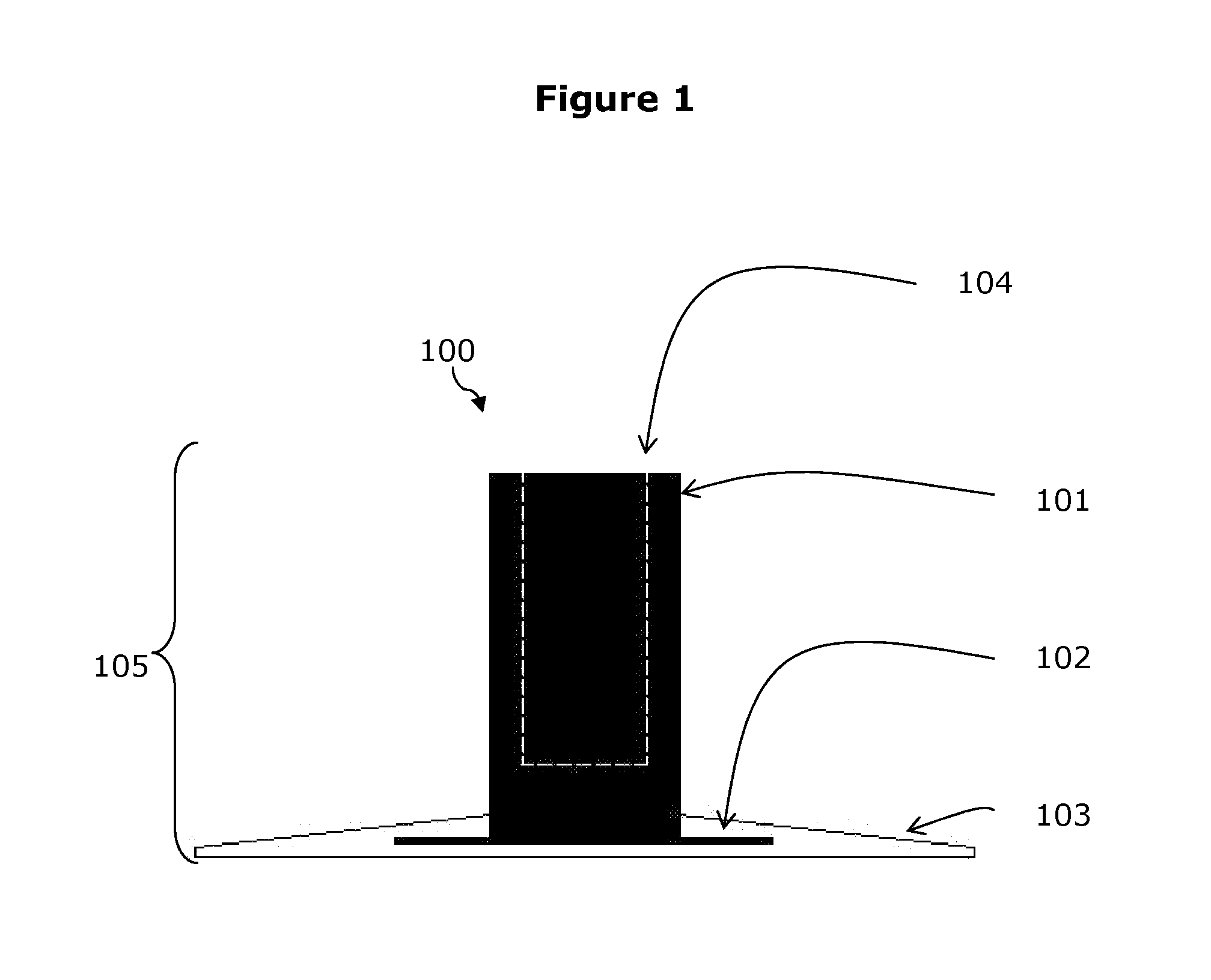
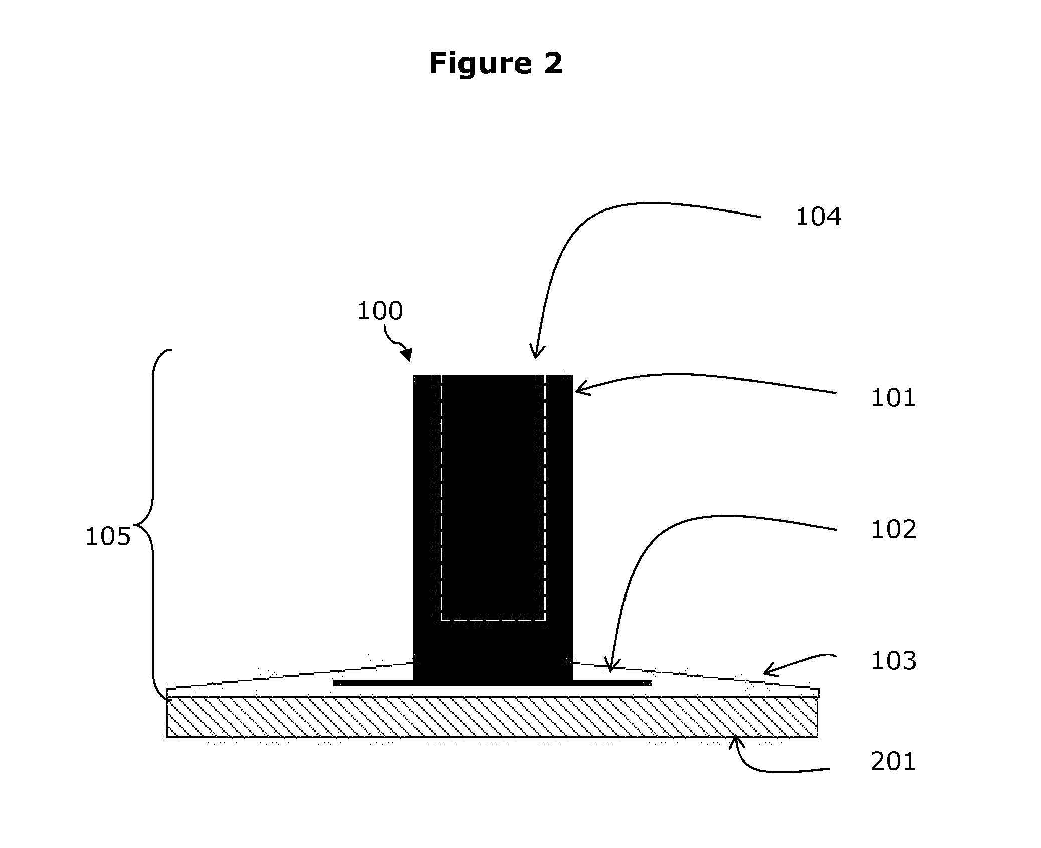
[0054]In this example, a metal composite hybrid part having the configuration shown in FIG. 1 and available from Click Bond, Inc. was adhesively bonded onto a carbon fiber epoxy resin composite plate using a thermoset epoxy adhesive. An epoxy adhesive was applied to the flat base of the part following the directions supplied by Click Bond, Inc. The part was placed onto a flat carbon epoxy composite plate.

[0055]A toughened carbon epoxy composite plate was made using Toray Industry aerospace grade T800 prepreg applied as 24 plies in a (0° 45° 90°−45°) repeat configuration. The composite plate was consolidated using the manufacturers curing cycle recommendation in an autoclave. The final plate was cut into 3″×3″ format pieces that were about ⅛″ thick.

[0056]The glass epoxy base of the Click Bond part and the carbon epoxy composite substrat...

Example

EXAMPLE 2

Attachment of a Metal Composite Hybrid Part to a Carbon Fiber Epoxy Resin Plate Using an Exemplary Adhesive and Process of the Present Invention

[0057]In this example, a metal composite hybrid part having the configuration shown in FIG. 1 and available from Click Bond, Inc. was adhesively bonded onto a carbon fiber epoxy resin composite plate using an exemplary adhesive formulation and bonding process of the present invention.

[0058]The adhesive formulation was made by uniformly dispersing about 0.5% by weight of carbon black and about 0.5% by weight of titanium dioxide (by weight of the polymer base) into a thermoplastic polyurethane dispersion, supplied by Sanyo Chemical Industries. About 20% by weight of the polymer base Vectran® TH1670 polyarylate short chopped fiber (0.5 mm) from Kuraray Co., Ltd., was blended uniformly into the dispersion. The adhesive was hand brushed onto the glass fiber-reinforced base of the part and dried in an oven at about 60° C. for about 30 min...

Example

EXAMPLE 3

Attachment of a Metal Composite Hybrid Part to a Carbon Fiber Epoxy Resin Plate Using Another Exemplary Adhesive Formulation and Process of the Invention

[0062]In this example, a metal composite hybrid part having the configuration shown in FIG. 1 and available from Click Bond, Inc. was adhesively bonded onto a carbon fiber epoxy resin composite plate using an adhesive formulation and bonding process described in this invention.

[0063]The adhesive formulation was made by uniformly dispersing about 0.5% by weight of carbon black (by weight of the polymer base) into a thermoplastic polyurethane dispersion, supplied by Sanyo Chemical Industries. No titanium dioxide or other additive was used in the formulation. About 20% by weight of the polymer base Vectran® TH1670 polyarylate short chopped fiber (0.5 mm) from Kuraray Co., Ltd., was blended uniformly into the dispersion. The adhesive was hand brushed onto the glass fiber-reinforced base of the part and dried in an oven at about...


PUM

PropertyMeasurementUnit
Temperatureaaaaaaaaaa
Lengthaaaaaaaaaa
Lengthaaaaaaaaaa

Abstract

The present invention relates to using an adhesive and process for heating, curing, joining, attaching and detaching a part article from a body substrate structure. Described are polymeric adhesive compositions and methods of curing using a radiation apparatus for rapid adhesive bonding and attaching a fastener part to a structure surface. The adhesive composition contains additives that directly or indirectly absorb projected radiation from a radiation apparatus to rapidly and uniformly melt the adhesive and bond the surface of the part material onto the surface of the substrate material. A process is also described to reverse the adhesive bonding and detach the fastener part from the substrate.

Description

CROSS REFERENCE TO RELATED APPLICATIONS[0001]This application claims the benefit of priority under 35 U.S.C. § 119(e) to U.S. Provisional Patent Application Ser. No. 60 / 969,750 filed Sep. 4, 2007; and under 35 U.S.C. § 120 to U.S. patent application Ser. No. 11 / 214,306, filed Aug. 29, 2005, the contents of which are fully incorporated herein by reference in their entirety.FIELD OF THE INVENTION[0002]Metal, composite and metal composite hybrid parts are attached to metal or composite surfaces in the manufacture of transportation body structures, such as aircraft fuselage or automobile body structures. The present invention relates to adhesive compositions including polymeric adhesives, and radiation apparatus for rapid adhesive bonding and attaching articles, for example, parts to a surface or to each other. A process is also described to reverse the adhesive bonding and detach the parts. In particular, the present invention relates to using an adhesive and process for heating, curin...

Claims


Application Information

Patent Timeline
IPC IPC(8): B32B38/10B29C65/14C09J133/24C09J175/04C09J133/12C09J133/06C09J163/00
CPCB29C35/02B29C65/483B29C65/1416B29C65/1419B29C65/1422B29C65/1435B29C65/1438B29C65/486B29C65/5057B29C65/522B29C65/524B29C65/526B29C65/7841B29C66/721B29C66/742B29C66/92431B29C66/949B29C2035/0822B29K2105/06B29K2305/00B29K2307/00B29K2309/08B32B37/0046B32B38/0036B32B2310/0825C09J131/04C09J133/10C09J133/12C09J163/00B29C65/14B29C65/4815B29C66/472B29C65/4885B29C65/488B29C65/4865B29C66/474B29C66/53245B29C65/1483B29C65/44B29C65/5028B29C65/76B29C65/4835B29C65/485B29C65/489B29C65/00B29C66/112B29C66/1122B29C66/131B29C66/71B29C66/7212B29C66/72141B29C66/73755B29C66/7394B29L2031/3076B29K2307/04B29K2063/00B29K2079/085B29K2079/08B29K2077/00B29K2075/00B29K2067/00B29K2033/12B29K2023/083
Inventor KUBOTA, MASANORIKUBOTA, AYAKOKUBOTA, MUNETAKAKUBOTA, TAKUMA
Owner KUBOTA RES ASSOC
Why Eureka
Try Eureka