Solid electrolytic capacitor

a solid electrolytic capacitor and capacitor technology, applied in the direction of variable capacitors, capacitor dielectric layers, superimposed coating processes, etc., can solve the problems of capacitance decrease, dielectric layer adhesiveness decrease, etc., to achieve the effect of increasing the adhesiveness between the dielectric layer and the first conducting polymer layer, reducing capacitance, and reducing capacitan

Active Publication Date: 2009-05-21
SANYO ELECTRIC CO LTD
View PDF3 Cites 30 Cited by
  • Summary
  • Abstract
  • Description
  • Claims
  • Application Information

AI Technical Summary

Benefits of technology

[0013]It is preferable that the molecular weight of polyglycerol be at least 300 but less than 4000. By setting the molecular weight within the above-described range, the decrease of capacitance can be more effectively checked.
[0014]It is preferable that the content of the non-ionic surfactant in the first conducting polymer layer be from 0.0005 weight % to 0.005 weight %. By setting the content to such range, adhesiveness between the dielectric layer and the first conducting polymer layer can be increased. Accordingly, the decrease of capacitance can be more effectively checked.

Problems solved by technology

However, the solid electrolytic capacitor with the conducting-polymer electrolyte layer formed therein has a problem that, when the solid electrolytic capacitor is preserved under a high-temperature condition, adhesiveness between the dielectric layer and the electrolyte layer decreases, thus causing a decrease of capacitance.

Method used


Image

  • Solid electrolytic capacitor
  • Solid electrolytic capacitor

Examples


experiment 1

Example 1

Step 1:

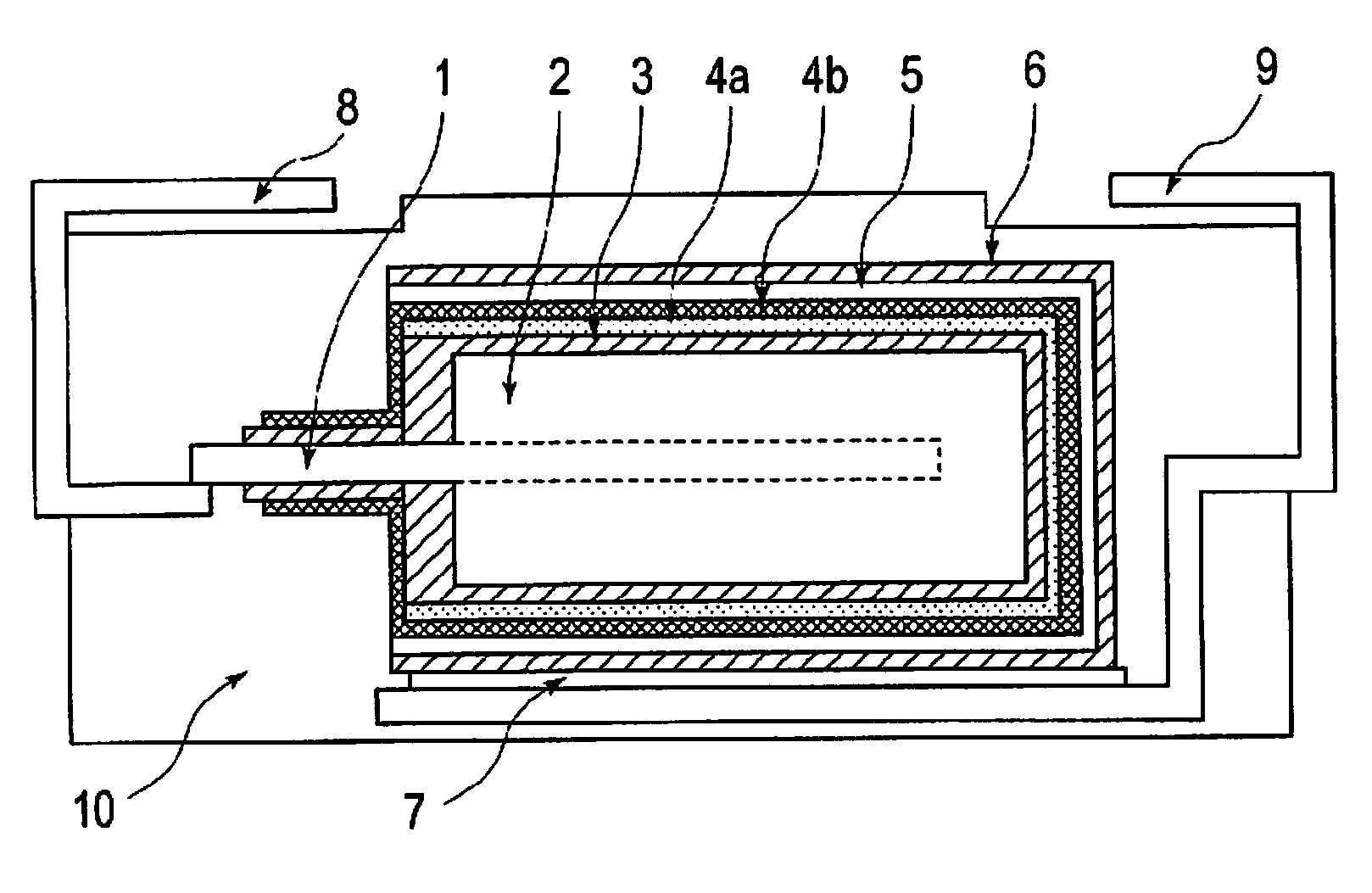
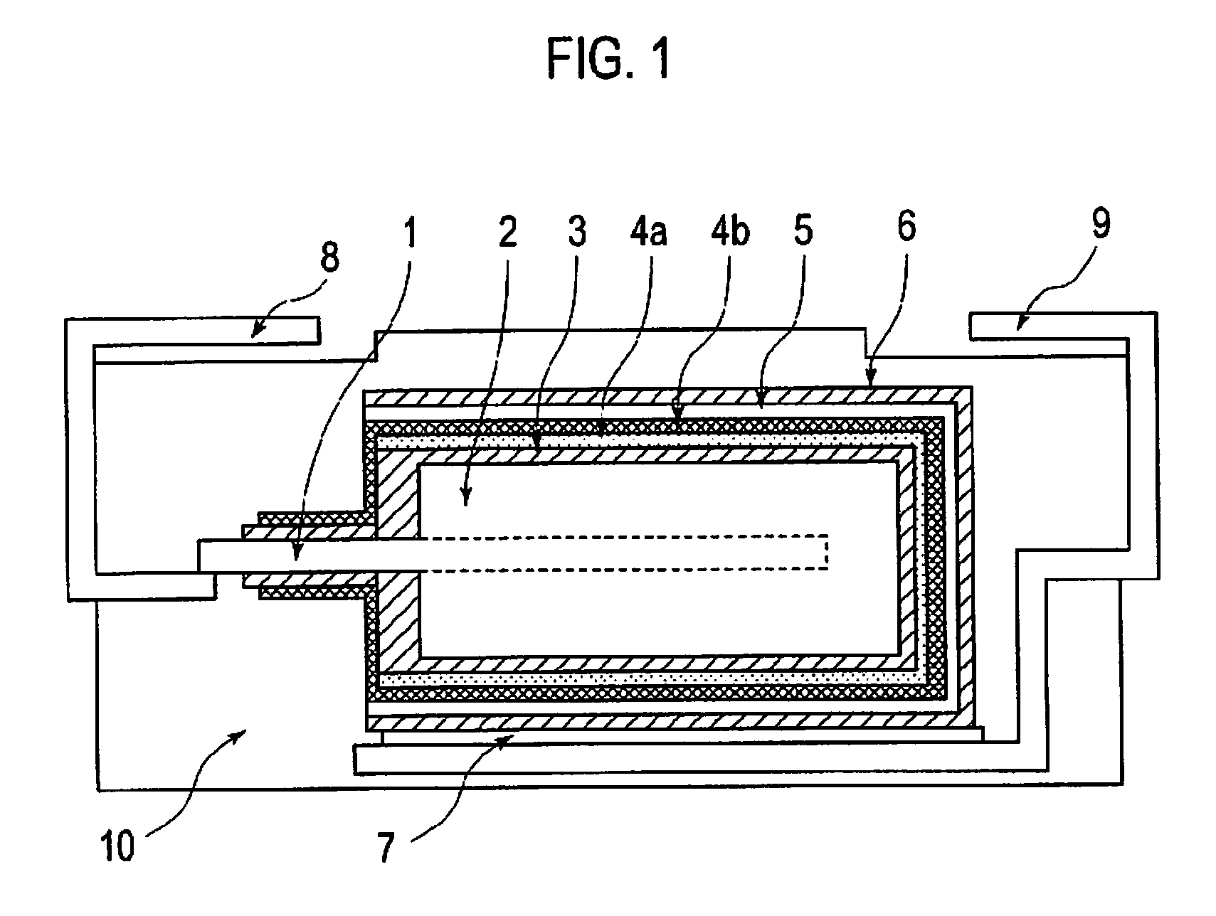
[0029]By sintering tantalum powder with a mean particle diameter of approximately 2 μm at a temperature of approximately 1400° C., an anode is prepared from a porous sintered compact in which a tantalum metal lead is buried. This anode is dipped in 0.1 weight % of an ammonium fluoride solution, which is kept at 40° C. The anode is anodized at a constant voltage of 10 V for 10 hours, so that a dielectric layer made of tantalum oxide is formed on the surface of the anode.

Step 2:

[0030]Next, the anode prepared at Step 1 is dipped in a 3,4-ethylenedioxythiophene solution containing approximately 0.001 weight % of polyethylene glycol (PEG: mean molecular weight is 1000) in relation to a monomer for 10 minutes. The 3,4-ethylenedioxythiophene solution thus used is a solution containing 2 mol / liter of 3,4-ethylenedioxythiophene. Thereafter, the anode is dipped in a solution containing 0.5 mol / liter of ammonium persulfate as an oxidizer for 10 minutes, and 3,4-ethylenedioxythi...

example 2

[0035]Solid electrolytic capacitor A2 is manufactured in a similar manner to Example 1, excepting that a solution containing approximately 0.001 weight % of polyglycerol (PG: mean molecular weight is 1000) in relation to a monomer is used for forming a first conducting polymer layer in place of the solution containing polyethylene glycol.

[0036]Similar to the foregoing manner, it is confirmed that the first conducting polymer layer contains polyglycerol and a dielectric layer contains fluorine.

example 3

[0037]Solid electrolytic capacitor A3 is manufactured in a similar manner to Example 1, excepting that a solution containing approximately 0.001 weight % of polyvinyl alcohol (PVA: mean molecular weight is 1000) in relation to a monomer is used for forming a first conducting polymer layer in place of the solution containing polyethylene glycol.

[0038]Similar to the foregoing manner, it is confirmed that the first conducting polymer layer contains polyvinyl alcohol and a dielectric layer contains fluorine.


PUM

PropertyMeasurementUnit
weight %aaaaaaaaaa
temperatureaaaaaaaaaa
mean particle diameteraaaaaaaaaa

Abstract

An aspect of the invention provides a solid electrolytic capacitor that comprises: an anode formed of a valve metal or an alloy mainly made of a valve metal; a dielectric layer formed on a surface of the anode; a first conducting polymer layer formed on the dielectric layer, the first conducting polymer layer containing a non-ionic surfactant; a second conducting polymer layer formed on the first conducting polymer layer; and a cathode layer formed on the second conducting polymer layer.

Description

CROSS REFERENCE TO RELATED APPLICATIONS[0001]This application claims priority based on 35 USC 119 from prior Japanese Patent Application No. P2007-301378 filed on Nov. 21, 2007, entitled “Solid Electrolytic Capacitor”, the entire contents of which are incorporated herein by reference.BACKGROUND OF THE INVENTION[0002]1. Field of the Invention[0003]The present invention relates to a solid electrolytic capacitor and a method for manufacturing the same.[0004]2. Description of Related Art[0005]A solid electrolytic capacitor is generally configured by: anodizing an anode made of a valve metal, such as tantalum or niobium, thereby forming a dielectric layer mainly made of an oxide on a surface of the anode; forming an electrolyte layer on the dielectric layer; and then forming a cathode layer on the dielectric layer. In such a solid electrolytic capacitor, it is preferable that its equivalent series resistance (ESR) be small.[0006]As a method for decreasing ESR, proposed is a formation of ...

Claims


Application Information

Patent Timeline
Patent Type & Authority Applications(United States)
IPC IPC(8): C25D11/02C23C28/00H01G9/025H01G9/07
CPCC23C28/00C25D11/02Y10T29/417H01G9/025H01G9/15C25D11/24
Inventor KIKUCHI, KAZUHITOTAKATANI, KAZUHIROYANO, MUTSUMIUMEMOTO, TAKASHINONOUE, HIROSHI
Owner SANYO ELECTRIC CO LTD
Why Eureka
Try Eureka