[0015]The main objective of the invention is to provide highly efficient
silicon thin film solar cells with superior light
trapping.
[0016]Another objective of the invention is to provide a cost effective production method for highly efficient
silicon thin film solar cells with superior light
trapping.
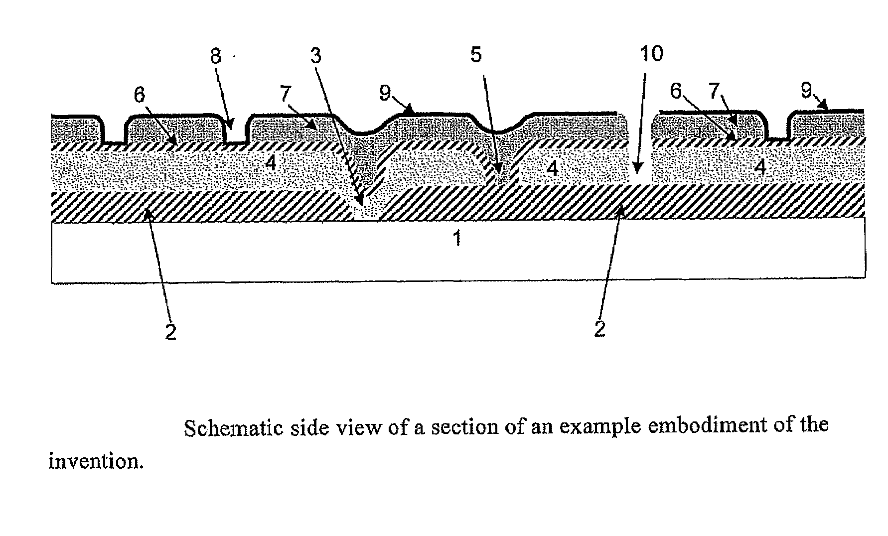
[0018]The invention is based on the realisation that superior light
trapping may be obtained by inserting a layer with a high diffuse reflectance between the transparent
conductive oxide layer and the
metal layer on the back side of the
semiconductor layers in an otherwise conventional silicon thin-film
solar cell. The diffuse reflective layer improves light trapping compared to having
metal directly in contact with the TCO for two reasons. Firstly, the diffuse reflective layer can have a higher
optical reflectance at its interface with TCO than metal in contact with TCO. This benefit is especially seen when only those metals that are inexpensive and that adhere well to TCO are considered (e.g.
nickel, chrome or
aluminium). Secondly, a diffuse reflector redirects light from regions with poor light trapping to other regions that are likely to have better light trapping. In this way, the diffuse reflector compensates for deficiencies in the spatial uniformity of the front-surface texture. The invention is further based on the realisation that by depositing the diffuse reflective layer by use of ink-jet printing, it may be deposited onto the TCO-layer with the necessary openings required for obtaining
electric contact between the metal and the TCO-layer. This approach to patterning the diffuse reflective layer has two primary benefits for the manufacturing of solar modules. Firstly, the formation of the diffuse reflective layer and the formation of the openings in this layer is all performed in the same step. Secondly, damage to the TCO-layer that would normally occur during the process of creating openings in the diffuse reflective layer is avoided.
[0034]A key
advantage of ink-jet printing the reflective layer including local openings directly during the deposition of this layer is that the need for using chemical
etching to make openings through the reflective layer is removed. An example of using chemical
etching for form openings through a resin layer with high diffuse reflectance is, for example, described in a published US
patent application by Young, US 20070007627. However, TCO-
layers are easily damaged by use of chemical
etching agents, a fact that has previously prevented the use of a TCO-diffuse reflector-metal structure on the back side of thin film solar cells / modules. The back side metal
contact layer may be deposited by
vapour deposition techniques,
evaporation,
sputtering etc. of a metallic phase onto the entire back side of the reflective
coating. Suitable metals for
vapour deposition include
nickel,
palladium,
titanium, silver, gold,
aluminium,
copper,
tungsten,
vanadium,
chromium, or any combination of these metals. Because the proposed structure relies primarily on the diffuse reflector layer to provide high internal back-surface reflectance, the
optical reflectance of the metal is not critical and this allows a wide range of metals to be considered. The thickness of the deposited metal layer, or stacked
system of metal
layers, should advantageously have a
total thickness in the range from 0.1 to 1 μm. Other possible techniques for depositing the metal layer(s) are electroless or electro plating. Suitable metals for plating include
nickel,
palladium, silver, gold,
copper,
chromium,
tin, or any combination of these materials. The invention is not restricted to these choices of metals, it may apply using any material that provides a good
electric contact with the underlying TCO layer, good electrical conductance, compatibility with the formation of contacts to carry the
electric current to an external load, and resistance towards any disruptive force / physical condition associated with normal use of solar panels during the expected lifetime of a solar panel. This may include known electric conducting plastics and / or other
polymer formulations such as carbon polymers, etc.
[0036]The pattern of openings in the diffuse reflective layer is adjusted to minimize the combined optical and electrical losses associated with contact between the metal and TCO layers. These contacts need to be few and far between to obtain the maximum benefit from the improved light trapping provided by the diffuse reflective layer, but they need to be numerous and closely spaced to minimize the electrical resistance loss due to lateral current flow in the back-side TCO. A typical coverage fraction for the openings is between about 1% and 10% with spacing between contacts between about 100 μm and 1 mm.
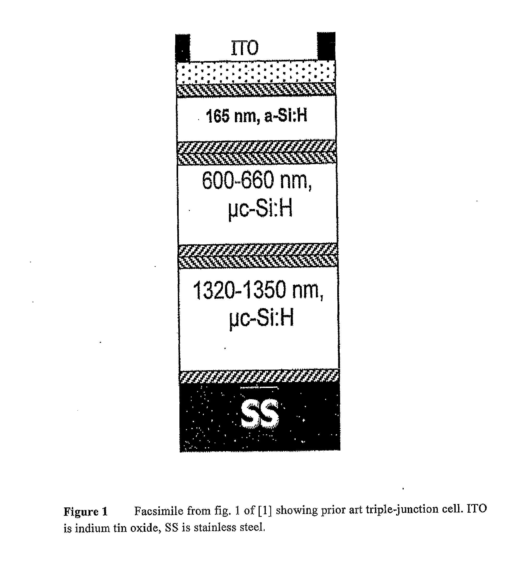
[0038]The
amorphous silicon and the multicrystalline silicon that form the multi junction thin-film solar conversion layers may be deposited by use of any known or conceivable technique that is compatible with TCO-coated glass. Possible techniques include, but are not limited to,
plasma enhanced chemical
vapour deposition (PECVD), hot wire chemical vapour deposition,
very high frequency plasma enhanced chemical vapour deposition,
sputtering, or
electron-beam deposition. Only PECVD has been developed to the scale required for commercial production in solar applications, but research continues in the other techniques, which offer the potential for faster deposition and / or reduced equipment cost.

