

Method of forming an oxide thin film
- Summary
- Abstract
- Description
- Claims
- Application Information
AI Technical Summary
Benefits of technology
Problems solved by technology
Method used
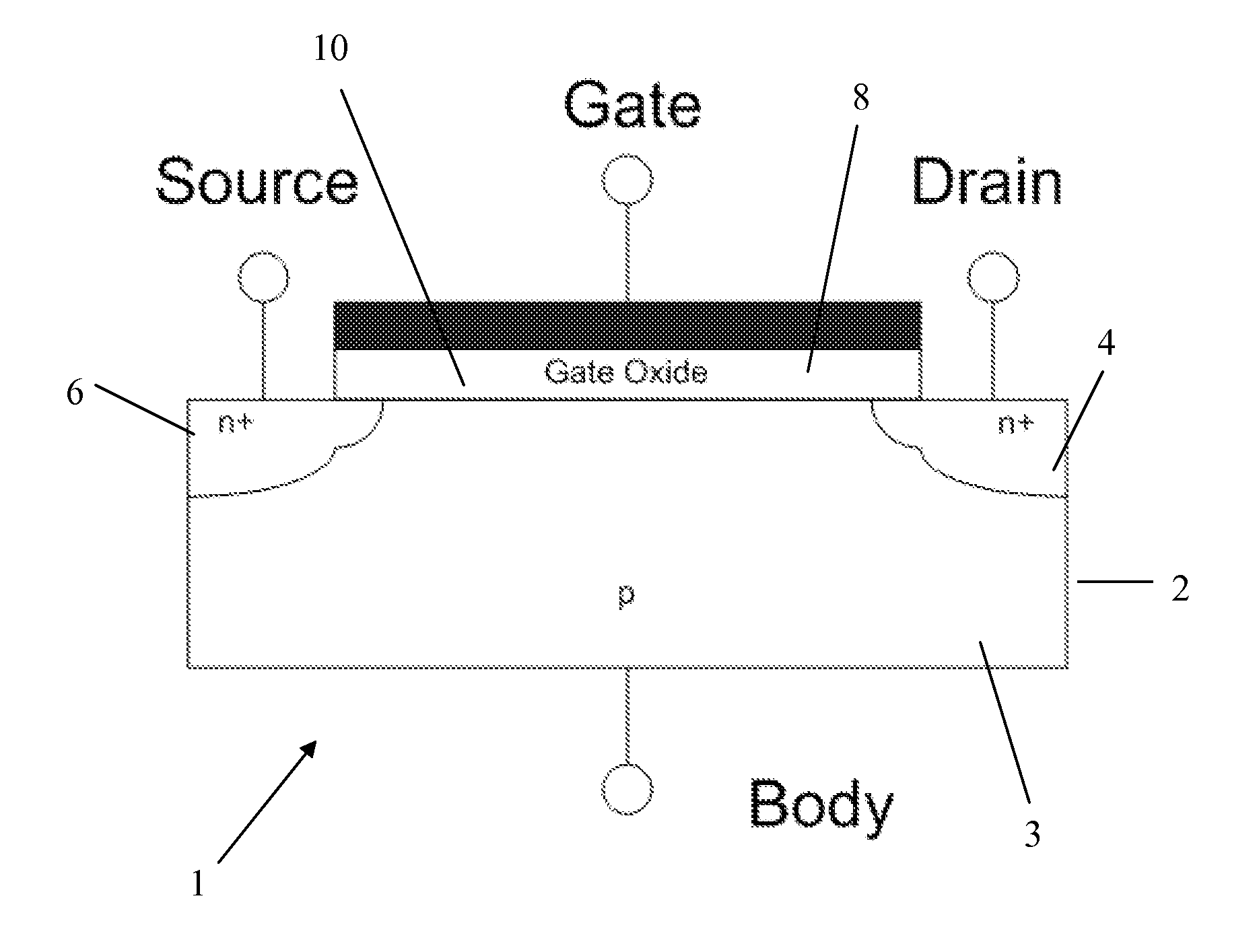
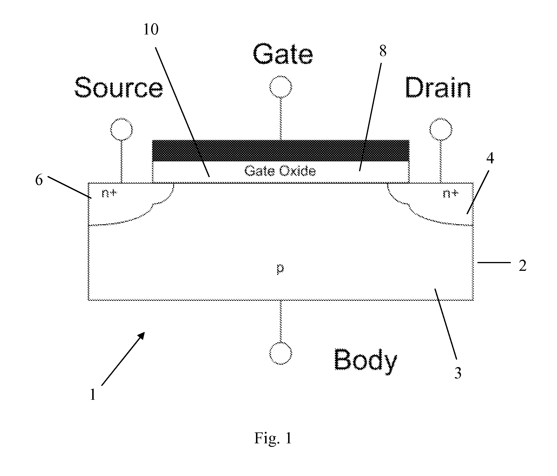
Image

Examples
example 1
Deposition of 5 nm HfO2 Thin Film at 200° C.
[0050]In an ALD reaction chamber one silicon substrate was introduced without treatment and one silicon substrate was cleaned by diluted HF-last solution (1 ml of methanol, 9 ml of water, and 0.75 ml of fluoric acid 40%) for 90 s just before introduction.
[0051]The two substrates were directly introduced in the preheated chamber (200° C.).
[0052]The hafnium tert-butoxide (Hf[OC(CH3)3]4) source was heated at 40° C.
[0053]The acetic acid precursor source was heated at 35° C.
[0054]The pipelines between the sources of liquid precursor and the atomic layer deposition chamber were heated at 70° C.
[0055]The deposition chamber was heated at 200° C.
[0056]A continuous flow of 10 sccm of nitrogen was introduced into the deposition chamber during the whole process. Under these conditions the pressure in the deposition chamber was 0.17 torr.
[0057]The deposition of 5 nm HfO2 film is made via 100 ALD cycles, each ALD cycle including:[0058]Opening the hafniu...
example 2
Deposition Rate of HfO, Thin Film at Temperatures from 100-300° C.
[0065]The experiment of Example 1 was repeated under deposition chamber temperatures of 100, 150, 175, 250 and 300° C. Other conditions remained the same. The deposition rates at different temperatures are depicted in FIG. 4, which shows a deposition plateau of 0.5 Å per cycle in the region from 175° C. to 250° C. Favourable deposition rates may be expected in this region, while avoiding the need for high temperatures in the deposition chamber.
example 3
Titanium Dioxide and Acetic Acid
[0066]The experiment of Example 1 was repeated using acetic acid and using Ti isopropoxide in instead Hf tert-butoxide to form a TiO2 gate oxide layer. The other experimental conditions were kept constant. Exemplary results were achieved in all cases. FIG. 5 shows reflectometry measurements of the TiO2 film formed with prior HF-last treatment. The graph shows good surface roughness and a grow rate of 0.62 Å per cycle.
PUM
| Property | Measurement | Unit |
|---|---|---|
| Temperature | aaaaa | aaaaa |
| Temperature | aaaaa | aaaaa |
| Temperature | aaaaa | aaaaa |
Abstract
Description
Claims
Application Information