
Organic electroluminescent device

a technology of electroluminescent devices and electroluminescent devices, which is applied in the direction of thermoelectric devices, organic chemistry, platinum organic compounds, etc., can solve the problems of increasing the drive voltage, reducing the power efficiency per amount of luminescence, and inevitably reducing durability of the device, so as to achieve excellent emission properties and reduce the drive voltage

Active Publication Date: 2010-07-08
UDC IRELAND
View PDF5 Cites 89 Cited by
  • Summary
  • Abstract
  • Description
  • Claims
  • Application Information

AI Technical Summary

Benefits of technology

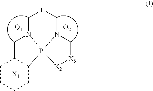
[0042]Q1 and Q2 have a great influence mainly on the emission wavelength and the effect of the invention is marked in a blue region so that they are preferably pyridine, pyrimidine, pyrazine, imidazole, or pyrazole having a blue light emitting structure, more preferably pyridine or pyrimidine. Of these, the following structures are still more preferred, with (Ia) being most preferred.
[0043]X1 represents a 6-membered ring containing one or more nitrogen atoms. The 6-membered ring may have a substituent. Examples of the substituent include those listed in the substituent group A. From the standpoint of chemical stability, halogen atoms, a cyano group, alkyl groups, aryl groups, heteroaryl groups, a silyl group, alkylamino groups, and arylamino groups are preferred. These substituents may be substituted further with another substituent. Examples of the another substituent include those listed in the substituent group A. The another substituent is preferably a halogen atom, more preferably a fluorine atom. As the substituent of X1, halogen atoms (especially preferably, a fluorine atom), a cyano group, alkyl halide groups (especially preferably, a perfluoromethyl group, a perfluoroethyl group, and a perfluoropropyl group), and alkyl groups are preferred, with a fluorine atom being most preferred.
[0045]From the standpoint of heat stability, X1 is preferably coordinated to Pt through a carbon atom. From the standpoint of heat stability, X1 is preferably an aromatic ring.
[0046]X1 has a great influence mainly on the emission wavelength and the effect of the invention is marked in a blue color region so that it has preferably a blue light emitting structure. The following are specific preferred structures and of these, (Ih) has the most preferred structure.
[0047]X2 represents a sulfur atom, a phosphorus atom, an oxygen atom, or a nitrogen atom and these atoms may have a substituent.

Problems solved by technology

This means that due to an increase in IP and decrease in Ea, an injection barrier between an adjacent layer on the cathode side and LUMO level rises, which usually results in such a problem that drive voltage increases.
An increase in the drive voltage causes a reduction in power efficiency per amount of luminescence.
In addition, a large electric field load is applied to the device so that the device inevitably has reduced durability.
These problems have not yet been solved even by the use of the organic EL devices described in, for example, Japanese Patent Laid-Open Nos. 2006-261623 and 2006-93665.

Method used


Image

  • Organic electroluminescent device
  • Organic electroluminescent device
  • Organic electroluminescent device

Examples


synthesis example 1

[0280]The following Exemplified compound 1 was synthesized.

[0281]A THF solution of Compound a (20.0 g, 56.2 mmol, 1.0 equivalent) was cooled to −78° C. in a nitrogen atmosphere and while stirring, the resulting solution was added dropwise to butyllithium (36.9 mL, 59.0 mmol, 1.05 equivalents) gradually. After stirring for 30 minutes as was, the resulting mixture was raised to room temperature while feeding the mixture with a carbon dioxide gas that was caused to pass through a calcium chloride tube. Then, a saturated aqueous solution of ammonium chloride was added to the reaction mixture, followed by extraction with ethyl acetate. The organic phases were combined, dried, and concentrated. The residue thus obtained was purified by a silica gel column to obtain 6.99 g (yield: 82%) of Compound b as a mixture with the raw materials.

[0282]A mixture composed of Compound b (7.2 g, 8.6 mmol, 1.0 equivalent), 2,6-difluoropyridyl-3-boric acid (5.3 g, 33.6 mmol, 1.5 equivalents), palladium ace...

synthesis example 2

[0305]The following Exemplified compound 2 was synthesized.

[0306]Compound c (1.0 g, 2.5 mmol, 1.0 equivalent) was dissolved in thionyl chloride (10 mL) and the resulting solution was heated and refluxed for 1.5 hours. After the reaction mixture was allowed to cool, the thionyl chloride was distilled off. The residue thus obtained was dissolved in methylene chloride (10 mL), followed by cooling to 0° C. Methanesulfonylamine (285 mg, 3.0 mmol, 1.2 equivalents) was added in portions to the resulting solution and the mixture was raised to room temperature. Water was added to the reaction mixture, followed by extraction with ethyl acetate. The organic phases were combined, dried, and concentrated. The residue thus obtained was purified by a column to obtain 980 mg (90%) of Compound d as a viscous liquid.

[0307]Platinum dichloride (325 mg, 1.22 mmol, 1.0 equivalent) and Compound d (530 mg, 1.22 mmol, 1.0 equivalent) were stirred in benzonitrile (10 mL) for 1.5 hours in a nitrogen atmospher...

synthesis example 3

[0310]The following Exemplified compound 3 was synthesized.

[0311]A triethylamine solution (10 mL) of Compound a (6.0 g, 16.8 mmol, 1.0 equivalent), ethyl phenyl hypophosphite (2.6 mL, 16.8 mmol, 1.0 equivalent), and tetrakistriphenylphosphine palladium (970 mg, 0.84 mmol, 0.05 equivalent) was heated for 1.5 hours at 100° C. After the reaction mixture was allowed to cool, a saturated aqueous solution of ammonium chloride was added to the reaction mixture, followed by extraction with ethyl acetate. The organic phases were combined, dried, and concentrated. The residue thus obtained was purified by a column to obtain 4.0 g (53%) of Compound e as a viscous liquid.

[0312]A mixture composed of Compound e (3.8 g, 8.5 mmol, 1.0 equivalent), 2,6-difluoropyridyl-3-boric acid (2.0 g, 12.8 mmol, 1.5 equivalents), palladium acetate (95 mg, 0.42 mmol, 5.0 mol %), triphenylphosphine (445 mg, 1.7 mmol, 0.2 equivalent), sodium carbonate (4.5 g, 43.0 mmol, 5.0 equivalents), dimethoxyethane (70.0 mL), ...


PUM

PropertyMeasurementUnit
thicknessaaaaaaaaaa
light transmittanceaaaaaaaaaa

Abstract

An organic electroluminescent device is provided and includes: a pair of electrodes; and a light emitting layer between the electrodes. The organic electroluminescent device has a layer containing a compound represented by formula (I).L represents a divalent linking group, Q1 and Q2 each independently represents an aromatic or aliphatic heterocycle coordinated to Pt through a nitrogen atom, X1 represents a 6-membered ring containing one or more nitrogen atoms, Q1, Q2, and X1 each independently may have a substituent, X2 represents a sulfur atom, a phosphorus atom, an oxygen atom, or a nitrogen atom, and X3 represents a carbon atom, a sulfur atom, or a phosphorus atom.

Description

[0001]This application is based on and claims priority under 35 U.S.C. §119 from Japanese Patent Application Nos. 2009-002056, 2009-186893, and 2009-201156, filed Jan. 7, 2009 and Aug. 11, 2009, and Aug. 31, 2009 respectively, the entire disclosures of which are herein incorporated by reference.BACKGROUND OF THE INVENTION[0002]1. Field of the Invention[0003]The present invention relates to an organic electroluminescent device (which may hereinafter be called “organic EL device”), an organometallic complex compound used therefor, and a light emitting apparatus and an illumination apparatus using the device.[0004]2. Background Art[0005]Research and development are being vigorously made on organic electroluminescent devices because they can emit light with a high luminance even by low voltage driving. In general, organic EL devices each has one or more organic layers including a light emitting layer and a pair of electrodes sandwiching them therebetween. For light emission, they utiliz...

Claims


Application Information

Patent Timeline
Patent Type & Authority Applications(United States)
IPC IPC(8): H01L51/54C07F15/00H10K99/00
CPCC07F15/0086H01L51/0087H01L51/5016C09K11/06C09K2211/185C09K2211/1029H10K85/346H10K50/11H10K2101/10
Inventor TAKADA, SAKIYAGI, KAZUNARIMURAKAMI, TAKESHIFUKUZAKI, EIJI
Owner UDC IRELAND
Learn More