Wireless temperature measurement system and methods of making and using same

a temperature measurement and wireless technology, applied in the field of sensors, can solve the problems of significant structural and aerodynamic problems, adversely affecting the performance of the turbine, and the effectiveness of certain temperatures and/or dynamic or harsh conditions, and achieve the effects of low mass, low mass, and small footprin

Active Publication Date: 2011-11-17
WIRELESS SENSOR TECH
View PDF6 Cites 72 Cited by
  • Summary
  • Abstract
  • Description
  • Claims
  • Application Information

AI Technical Summary

Benefits of technology

[0032]In accordance with the present invention, embodiments of the inventive system and methods for use in gas turbines preferably have a small footprint, low mass relative to the mass of the turbine blade, and thicknesses less than the gas phase boundary layer thickness, so that gas flow through the engine is not adversely affected by the profile of the sensor. Advantageously, embodiments of the temperature sensors also have low mass when compared to wire thermocouples. Such embodiments also preferably possess low thermal mass to facilitate a rapid response and avoid disturbing the convective heat transfer character

Problems solved by technology

While the mercury thermometer may be acceptable for measuring the temperature of the human body, it faces limitations in effectiveness above certain temperatures and/or under dynamic or harsh conditions.
However, embedding wires in the walls may cause significant structural and aerodynamic problems, including perturbing the flow of air used to cool blades and vanes.
This perturbation may affect the boundary layer of air next to the blade and may adversely impact turbine performance.
Due to the thermal mass of the wires and associated ceramic insulator layer, such devices can introduce significant measurement error.
Such techniques are not easily transferable to the gas turbine engine environment for temperature monitoring, however, because smoke or other particulates may scatter the light.
The extreme temperatures and velocities within a gas turbine engine also make it difficult to produce reliable infrared images.
Additionally, adsorption by dust, windows, flames, gases and other optical interference can produce errors.
However, thermal paints typically exhibit poor adhesion and thus require special techniques to survive the harsh environment in gas turbine engines, such as described in U.S. Pat. No. 5,720,554 to Smith, et al., “Apparatus and method for the calibration of thermal paint.” Other types of thermal paints having better adhesion are known, such as those described in Gregory et al, “Method of Preparing Ceramic Coatings for Temperature Measurement,” U.S. Pat. No. 5,338,566 and Gregory et al, “Ceramic Coatings for Temperature Measurement,” U.S. Pat. No. 5,135,795.
Previously-known temperature measurement apparatus, however, are not ideal for use in measuring the temperature of an operating turbine blade for a number of reasons.
As the heat resistant coating on the blade erodes, however, the trenches may become exposed and compromise the structural integrity of the blade.
In addition, the relatively large thermal mass of the connectors and any associated insulation ma

Method used


Image

  • Wireless temperature measurement system and methods of making and using same
  • Wireless temperature measurement system and methods of making and using same
  • Wireless temperature measurement system and methods of making and using same

Examples


example 1

[0102]The frequency offset data of one embodiment of a temperature sensor constructed in accordance with the principles of the present invention has been shown to be monotonic over a desired temperature range with repeatable results over multiple measurement sets. Data demonstrating the relationship between antenna resonant frequency and temperature are shown in FIG. 17, which was acquired utilizing direct network analyzer measurements. Testing showed that data taken during transition from a high temperature to a low temperature was substantially the same as data obtained during transition from a low temperature to a high temperature. These observations indicate that there is little or no hysteresis in the temperature sensor response after repeated heating / cooling cycles. The resolution for the temperature sensor was within −187 ppm / degrees Celsius in a temperature range from 25 to 1000 degrees Celsius. By comparison, previously known devices are reported to have a resolution of −34...

example 2

[0103]The accuracy of an embodiment of a temperature sensor constructed in accordance with the present invention was analyzed by comparing temperature determinations of the inventive sensor to the temperature of an oven. Results of these tests are presented in FIGS. 18A and 18B. As shown in the table of FIG. 18B, the testing demonstrated a strong correlation between the temperature determined with the temperature sensor and the oven temperature. These test results did not consider the oven temperature control resolution, and therefore the oven temperatures (25° C., 150° C., 200° C., 250° C.) may actually have been slightly more or less than the reported values. The temperature measurements of the temperature sensor of the present invention were conducted using a centroiding algorithm to calculate temperature from the harmonic output center frequency. For purposes of this testing, the temperature sensor included an off-the-shelf diode suitable for the limited temperature range of the...

example 3

[0104]The antenna of the temperature sensor of the present invention may be considered a micro-gap derivative of a transmission line antenna due to the narrow spacing between the antenna element and the ground plane. Typically, a transmission line antenna is a conductive wire about ¼ wavelength long and placed parallel to and very close (<0.01 wavelength) to a much larger ground plane surface. One end of the ¼ wave conductor is connected to the ground plane and the other end is not connected. Close to the grounded end of the conductor, the impedance of the strip is approximately 50 ohms and purely resistive. In such embodiments, the antenna elements and associated interconnects preferably comprise platinum, rhodium, iridium, platinum:rhodium alloys, palladium or refractory materials.

[0105]An embodiment of a micro-gap antenna was constructed in accordance with the present invention. This antenna was tested and produced the results shown in FIG. 19. The performance of the antenna has ...


PUM

PropertyMeasurementUnit
Temperatureaaaaaaaaaa
Distanceaaaaaaaaaa
Frequencyaaaaaaaaaa

Abstract

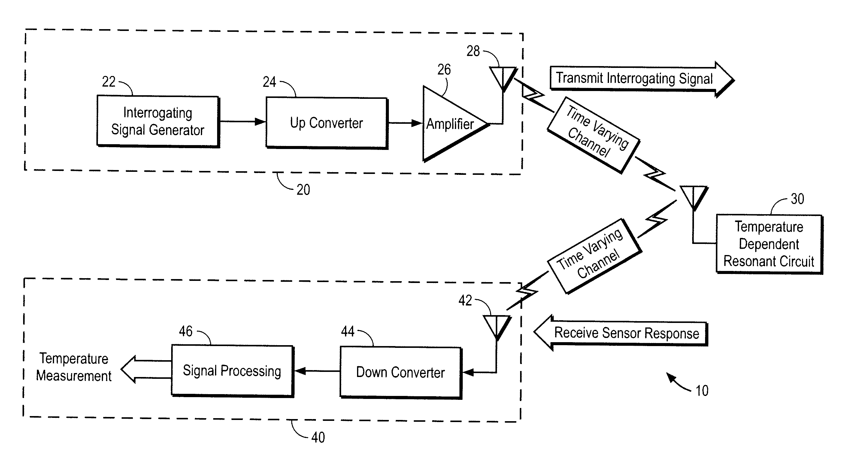
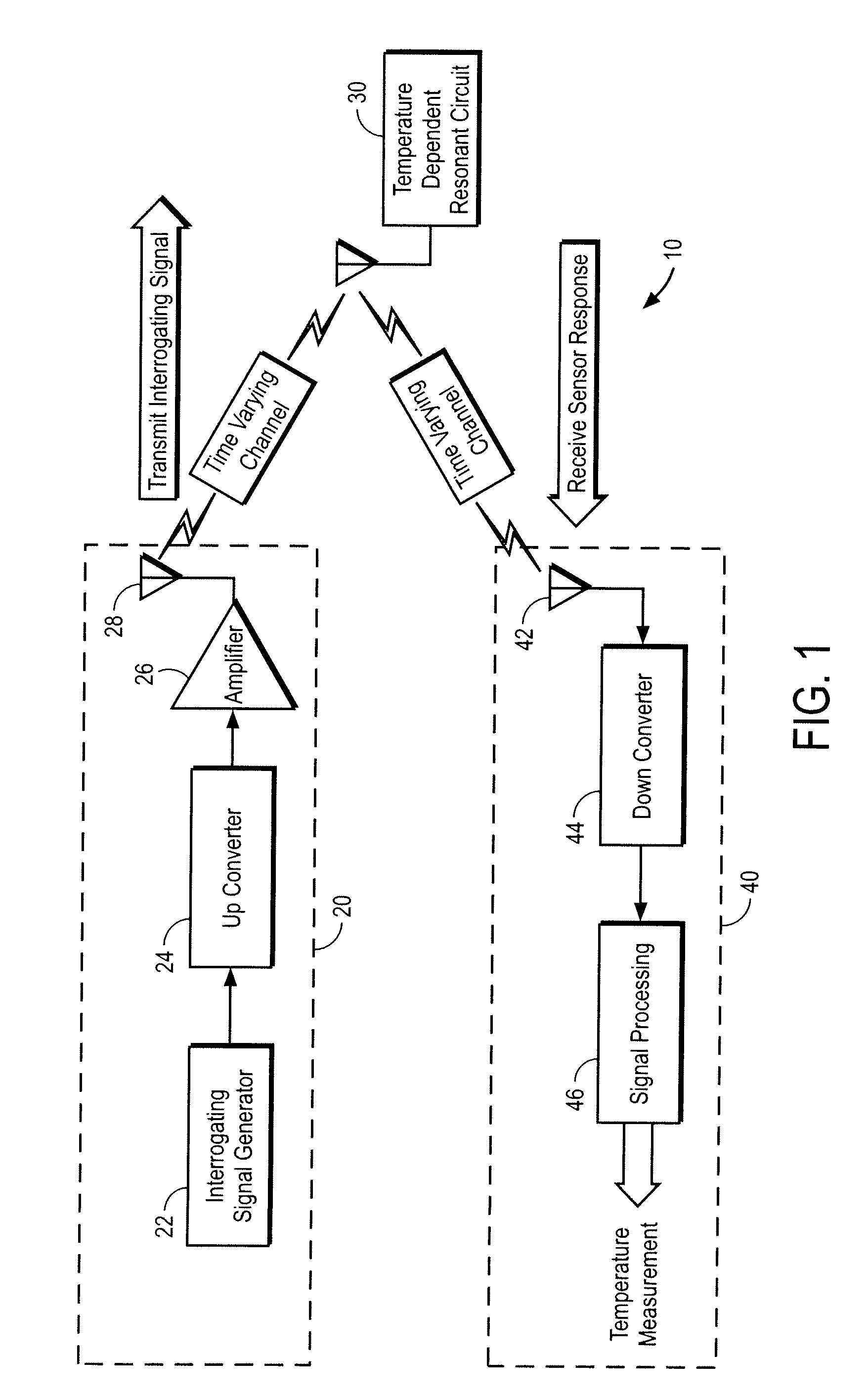
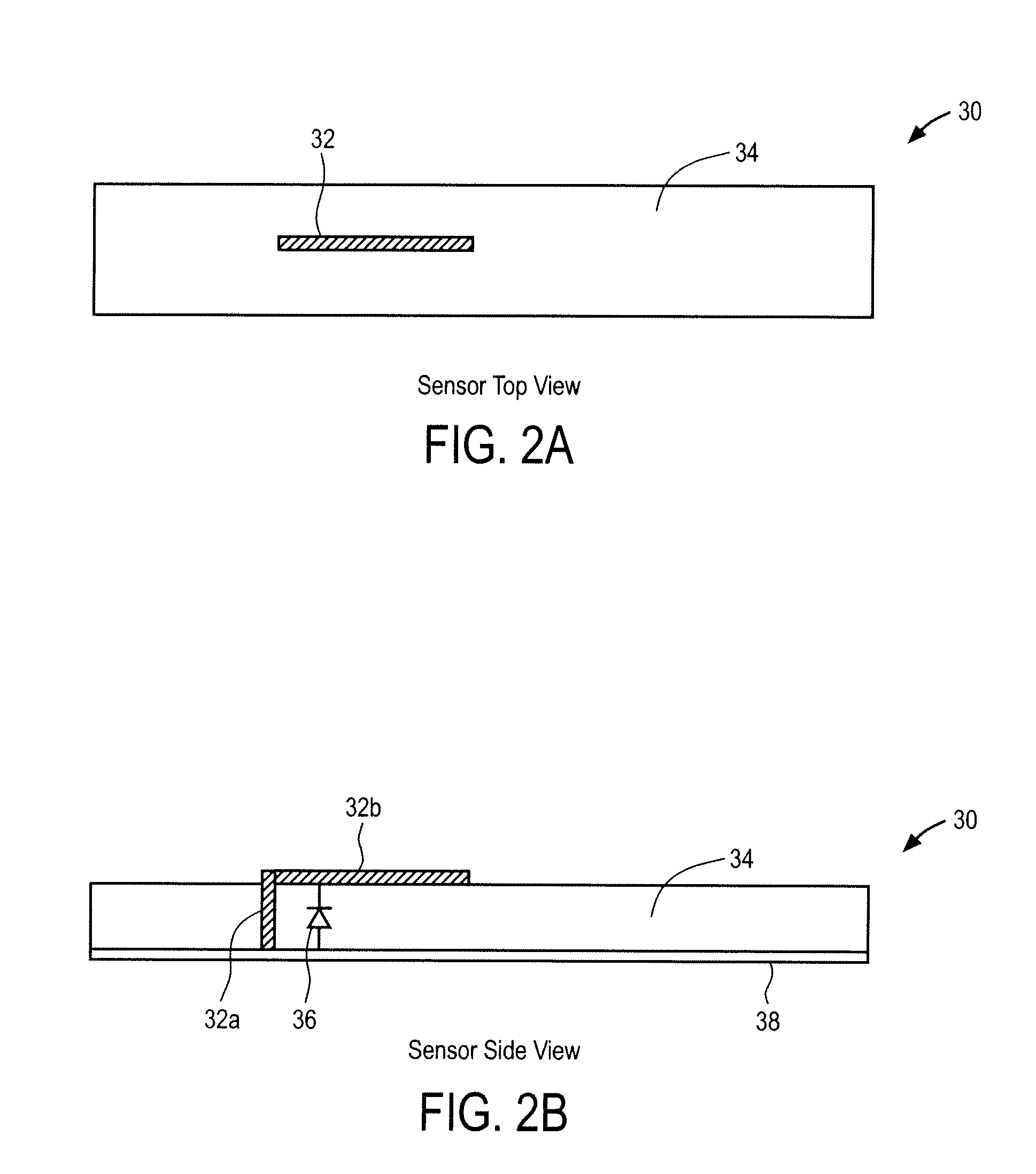
A temperature measurement system capable of operating in harsh environments including a temperature sensor having an antenna, diode, and dielectric layer disposed on the object of interest is provided, wherein the antenna includes a buried portion that extends through and is electrically coupled to the object of interest, and an exposed portion disposed upon an outer surface of the dielectric layer and the diode is coupled between the object of interest and the exposed portion of the antenna. The antenna is configured to receive interrogating signals from a transmitter, and to transmit response signals corresponding to the resonant frequency of the temperature sensor and its harmonics, which are indicative of the measured temperature of the object of interest. A receiver detects the response signals and correlates the frequency to a known temperature response of the dielectric material. Methods of making and using the temperature measurement system are also provided.

Description

STATEMENT REGARDING FEDERALLY SPONSORED RESEARCH OR DEVELOPMENT[0001]The United States Government may have certain rights in this invention pursuant to SIBR Contract N68335-08-C-0267 awarded by the United States Navy.FIELD OF THE INVENTION[0002]This invention relates to sensors, and in particular to wireless sensors, components thereof, that may be used to determine the temperature and / or heat flux in harsh environments.BACKGROUND OF THE INVENTION[0003]Numerous methods and devices are known for measuring temperature. For example, the mercury thermometer has existed for hundreds of years. While the mercury thermometer may be acceptable for measuring the temperature of the human body, it faces limitations in effectiveness above certain temperatures and / or under dynamic or harsh conditions. Such conditions may include the interior of an internal combustion engine or on a moving blade of a gas turbine.[0004]A gas turbine engine is an example of a device within which extremely high tempe...

Claims


Application Information

Patent Timeline
IPC IPC(8): G01K13/00
CPCF01D17/085G01K1/024G01K7/32Y10T29/49018Y02T50/672F05D2260/80H01P11/00G01K7/343Y02T50/60
Inventor GREGORY, OTTO J.CONKLE, JOHN R.BIRNBAUM, THOMAS J.
Owner WIRELESS SENSOR TECH
Why Eureka
Try Eureka