Calibration slide for fluorescence detection instruments and process of preparation

a fluorescence detection and slide technology, applied in instruments, fluorescence/phosphorescence, chemical methods analysis, etc., can solve the problems of incomparable readings, error readings, application in quantitative microarray analysis, etc., and achieve the effect of long shelf life and high photostability of fluorescence detection instruments

Inactive Publication Date: 2011-12-29
CAPITALBIO CORP +1
View PDF2 Cites 24 Cited by
  • Summary
  • Abstract
  • Description
  • Claims
  • Application Information

AI Technical Summary

Benefits of technology

[0016]The aim of this invention is to disclose calibration slides with high photostability and long shelf life for fluorescence detection instruments and process of making them.

Problems solved by technology
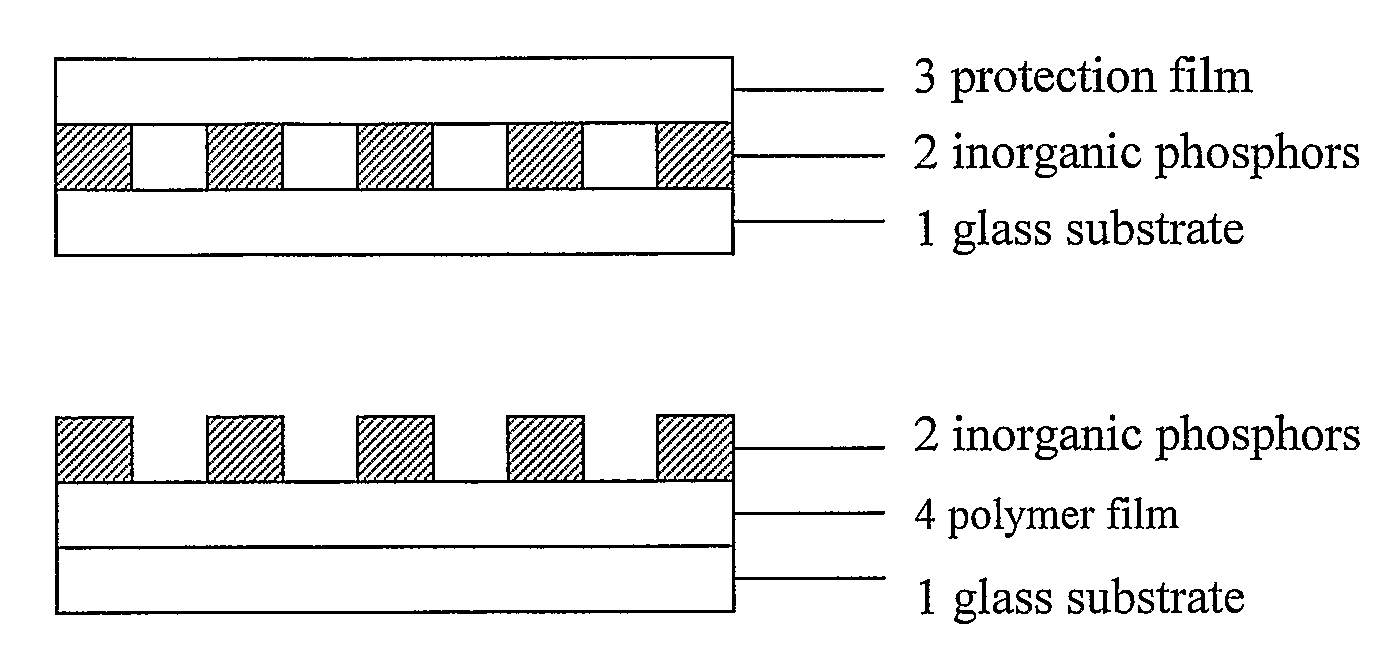
But there appear two problems which affect its application in quantitative microarray analysis.
For the individual scanners, the laser source inevitably fluctuates or even declines during operation and the confocal plane may also shift due to malfunctioned optical system, scanning accuracy also differs after long-term usage, which may cause error readings.
For the instruments from different manufacturers, they differ in design and manufactory of light source, light path as well as the detection system, which results in incomparable readings.
However, they are not suitable for fluorescence microarray scanners which employ glass slide as detection targets.
Organic Fluorescence dyes possess poor photostability and will photo-bleach after exposure to light.
However, among these materials, the problem with photobleaching of fluorescent dyes still could not be resolved.
But as the fluorescing material is again organic dye, simply encaged in inorganic matrix doesn't improve its photostability.
However, the manufactory method restricts its application in calibration with fine structures for microarray scanners.

Method used


Image

  • Calibration slide for fluorescence detection instruments and process of preparation
  • Calibration slide for fluorescence detection instruments and process of preparation
  • Calibration slide for fluorescence detection instruments and process of preparation

Examples


example 1

Preparation of Calibration Slides using Rare-Earth-SiO2 Complex as Fluorescing Material

[0034]1. Preparation of rare-earth-SiO2 complex

[0035]An aliquot of 2.2 ml of TEOS and 0.58 ml of anhydrous alcohol was mixed together and magnetically stirred in a 25 ml Erlenmeryer flask. Into the mixture, deionized water and 0.36 ml of 0.15 M hydrochloric acid aqueous solution was added dropwise to promote hydrolysis of TEOS. After reaction for 2 hours, a quantity of 10 ml of thulium chloride (TmCl3) solution was added. The gel was aged for 12 hours at room temperature. Tm—SiO2 complex was obtained after drying.

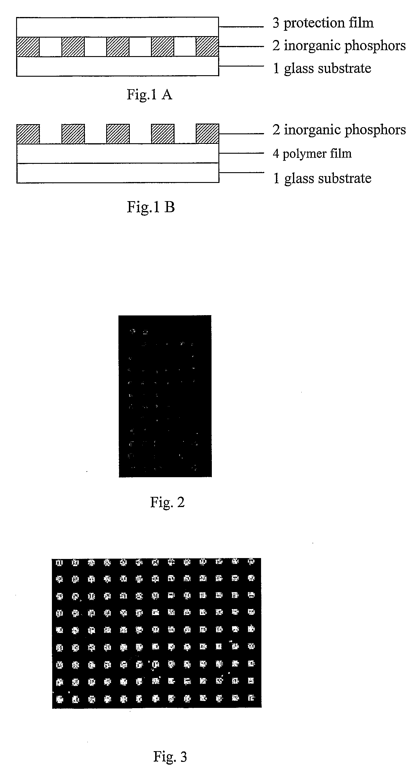
[0036]Four milligrams of the above said Tm—SiO2 rare-earth inorganic complex were added to 100 μL of 4% PVA aqueous solution. The mixture was sonicated till the particles were well dispersed and used as printing sample. GeneMachine Contact Arrayer was used to print the printing sample onto the surface of a clean microscope slide to produce the calibration slides.

[0037]The slide was scanne...

example 2

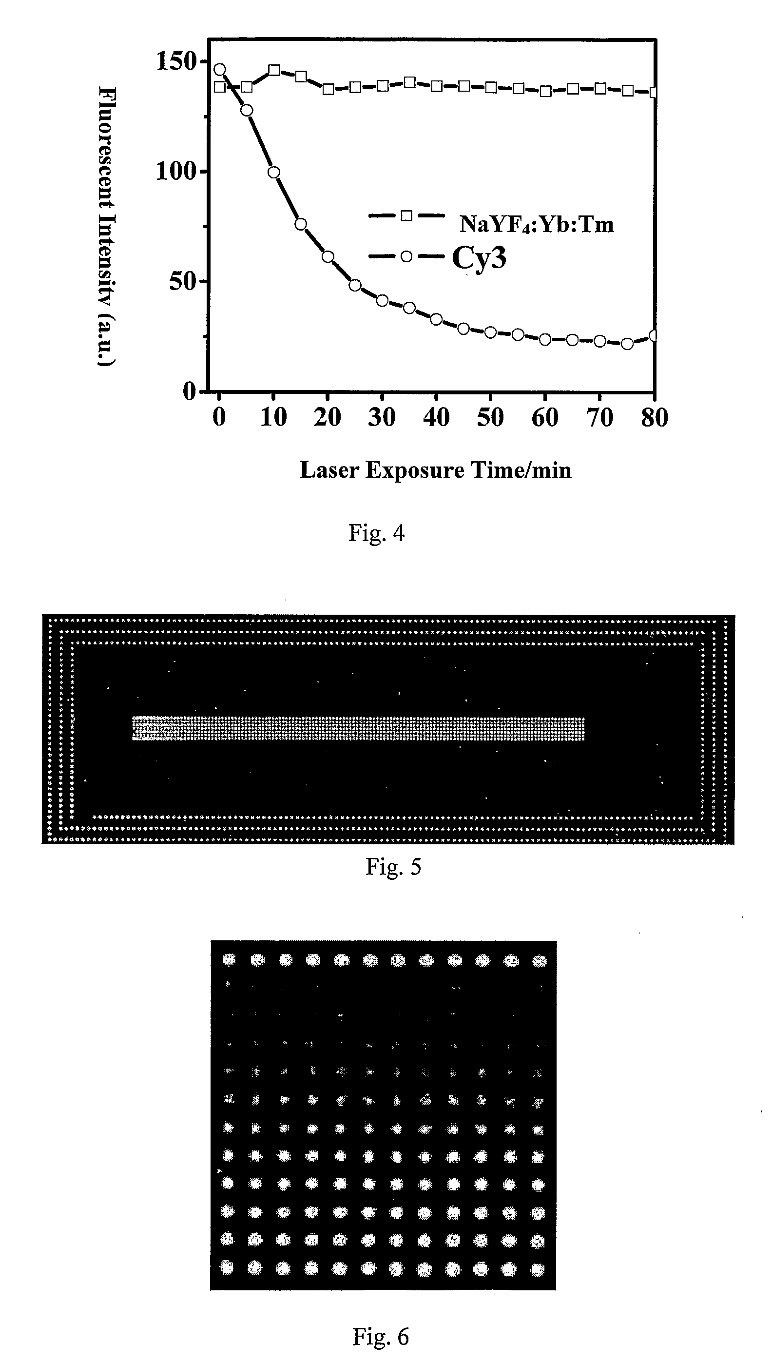
Preparation of Calibration Slides using Rare-Earth Complex NaYF4:Yb:Tm as Fluorescing Material

[0038]1. Preparation of NaYF4:Yb:Tm rare-earth complex

[0039]A sodium fluoride (NaF) solution was prepared by dissolving 2.1 g of NaF in 80 ml of deionized water. Solutions of 20 ml of 0.2 M Yttrium chloride (YCl3), 6 ml of 0.2 M ytterbium chloride (YbCl3) and 3 ml of 0.2 M TmCl3 were injected into the NaF solution. The mixture was stirred vigorously for 1 h at room temperature. The obtained precipitate was centrifuged at 4000 rpm, washed three times with deionized water, and dried at 60° C. The white powder of rare-earth complex was obtained after annealed at 400° C. for 5 h under nitrogen protection.

[0040]2. Preparation of calibration slide

[0041]The above said rare-earth complex was added to 10% Tween-20 aqueous solution. The calibration slides on clean glass slides were obtained following the same protocol as mentioned in Example 1.

example 3

Preparation of Calibration Slides using Rare-Earth Complex NaYF4:Tm as Fluorescing Material

[0042]1. Preparation of NaYF4:Tm rare-earth complex

[0043]A NaF solution was prepared by dissolving 2.1 g of NaF in 80 ml of deionized water. Solutions of 20 ml of 0.2 M YCl3 and 3 ml of 0.2 M TmCl3 were injected into the NaF solution. The mixture was stirred vigorously for 1 h at room temperature. The obtained precipitate was centrifuged at 4000 rpm, washed three times with deionized water, and dried at 60° C. The white powder of rare-earth complex was obtained after annealed at 400° C. for 5 h under nitrogen protection.

[0044]2. Preparation of aldehyde-modified slide

[0045]Five microscope slides were immersed in chromic acid solution (8 g K2Cr2O7+5 ml H2O+95 ml concentrated sulfuric acid) and cleaned thoroughly with Milli Q water. The slides were then immersed in 40 ml of 1% 3-aminopropyl triethoxysilane (APTES) ethanol solution for silanization. The reaction was continued for 1 h with rotation...


PUM

PropertyMeasurementUnit
diameteraaaaaaaaaa
diameteraaaaaaaaaa
thicknessaaaaaaaaaa

Abstract

The present invention relates to calibration slides for fluorescence detection instruments and processing method of making them. The aim of this invention is to disclose calibration slides with high photostability and long lifetime for fluorescence detection instruments. The calibration slides are fabricated by patterning calibration spot arrays of modified inorganic phosphors on the glass slide. The process for producing a calibration slide comprises the following procedure: 1) Dispersing the inorganic phosphors of rare-earth doped complex in water; 2) Patterning the affay of the above suspension on the glass slide. The calibration slides in the present invention employ a very stable fluorescing material that is insensitive to photobleaching, has long lifetime and stability under mild storage condition. The calibration slides in the present invention can be used to calibrate and test for some fluorescence instruments, i.e. microarray scanner, fluorescent microscopy, fluorescence spectrometer, fluorescent multiwell-plate reader

Description

TECHNICAL FIELD[0001]The present invention relates to calibration slides for fluorescence detection instruments and process of making them. More particularly, the present invention relates to rare-earth ion doped inorganic arrays for calibration of fluorescence microarray scanners and process of making them.BACKGROUND ART[0002]The arising of microarray technique since the end of last century has speeded the progress of Human Genome Project as well as many other research projects requiring high-through put analysis. Fluorescence microarray scanner has then become the most recently and successfully developed fluorescence detection instrument for the purpose of microarray chip analysis. But there appear two problems which affect its application in quantitative microarray analysis. For the individual scanners, the laser source inevitably fluctuates or even declines during operation and the confocal plane may also shift due to malfunctioned optical system, scanning accuracy also differs ...

Claims


Application Information

Patent Timeline
Patent Type & Authority Applications(United States)
IPC IPC(8): G01N33/00G01N21/01G01N21/27G01N21/64
CPCG01N21/278Y10T436/255G01N21/6452
Inventor GE, YUYANG, WENJUNZHAO, SHUYINGGUO, LIANGHONGCHENG, JING
Owner CAPITALBIO CORP
Why Eureka
Try Eureka